Post 655
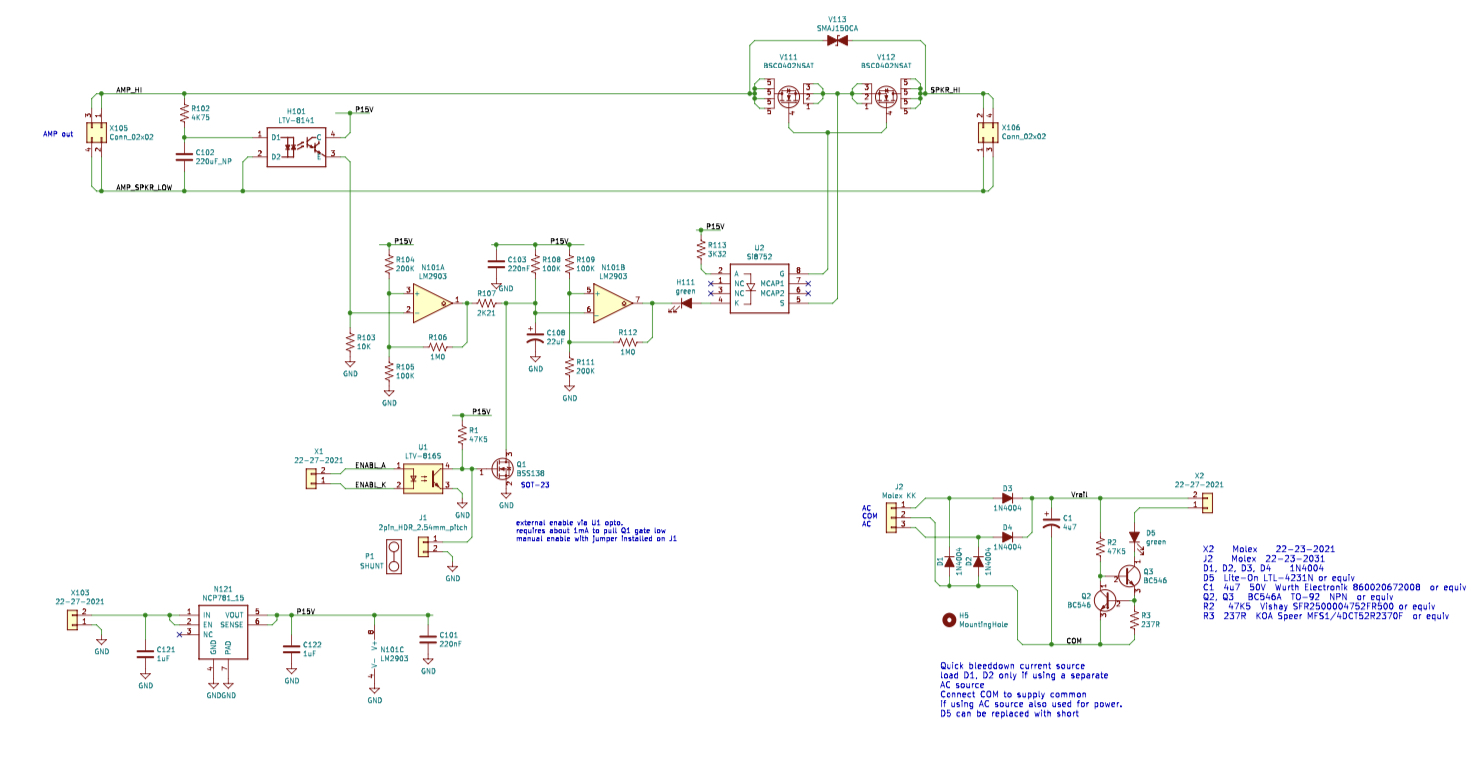
The Gen2 has its power supply isolated from the speaker negative or ground - allowing use in BTL (non zero volts negative terminal) amps. Hence, the PSU connection needs its own ground.
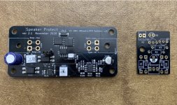
There is also a remote quick shutdown connection, that when used in conjunction with an open collector type logic circuit, allows the SSR to turn off instantly to prevent speaker turn off thump. The bonus unpopulated through hole board that comes with the SSR allows you to make such a circuit with a few parts. Or if you are handy with microcontrollers or Arduino, you can easily provide this signal yourself. This bonus instant off controller board is powered by the secondaries of the power trafo. The moment power is switched off, the bonus controller switches the SSR off. Connect X2 to X1 (pin 1 to pin1 and pin2 to pin2). By making the controller board separate, it can reside closer to the PSU. The controller board can switch two SSRs off by putting the connections in series.
Note that if you are not using the external instant shutoff feature, a jumper must be installed at J1.
The Gen2 has its power supply isolated from the speaker negative or ground - allowing use in BTL (non zero volts negative terminal) amps. Hence, the PSU connection needs its own ground.
There is also a remote quick shutdown connection, that when used in conjunction with an open collector type logic circuit, allows the SSR to turn off instantly to prevent speaker turn off thump. The bonus unpopulated through hole board that comes with the SSR allows you to make such a circuit with a few parts. Or if you are handy with microcontrollers or Arduino, you can easily provide this signal yourself. This bonus instant off controller board is powered by the secondaries of the power trafo. The moment power is switched off, the bonus controller switches the SSR off. Connect X2 to X1 (pin 1 to pin1 and pin2 to pin2). By making the controller board separate, it can reside closer to the PSU. The controller board can switch two SSRs off by putting the connections in series.
Note that if you are not using the external instant shutoff feature, a jumper must be installed at J1.
Last edited:
OK, thanks for the quick reply X.
To sum up the connections for a normal stereo power amp build - the following should be correct.
1. Wire Amp output to X105 with positive to Amp Hi and GND to Amp Low.
2. Wire speaker binding posts to X106 with positive to Speaker Hi and GND to Speaker Low.
3. Power supply to X103 with amp GND (0V) to pin 1 and the positive amp rail DCV to pin 2 (40VDC in my case).
4. X1 is not used.
5. Jumper installed on J1 - I assume the assembled and tested pcb will be supplied with that jumper in place?
Yes to all the above. I am not sure if the manufacturing house will provide the jumper for the header pins J1. But I’ll throw one in if they don’t.
Hi Folks,
I have great news here, the Gen2 SSRs are delivered! They look well packed and individually packed in anti static bags. Bonus boards separately packed and broken off already. The J1 shunts are already installed. I tested one and it works well.

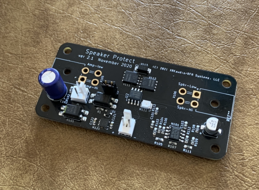
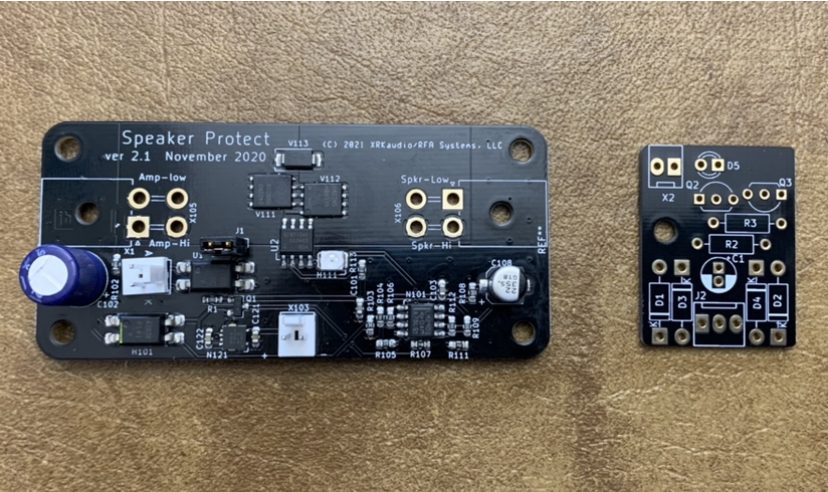
I have great news here, the Gen2 SSRs are delivered! They look well packed and individually packed in anti static bags. Bonus boards separately packed and broken off already. The J1 shunts are already installed. I tested one and it works well.
Attachments
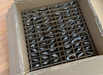


That is all looking good X, thanks for the update, according to the box - you only have 77 more boards to test. 😉
I have tested only 2 so far. 🙂
I’ll test them as I go “JIT” before shipment rather than opening each of the sealed bags now. So far so good.
I’ll test them as I go “JIT” before shipment rather than opening each of the sealed bags now. So far so good.
Good luck with the testing an all of the other boards X.
I assume your Etsy store will email shipping details as you get these sent out?
I assume your Etsy store will email shipping details as you get these sent out?
Yes. Planning to start shipping out this weekend. Can’t promise everyone’s orders will get shipped this weekend.
No hurry with my order to be shipped X - don't forget I've also got an order in with you for PCBs for All Cees power supplies and Dibyah chip amps
Thanks for the reminder. Actually, everyone who has special orders like this should remind me.
Thanks,
X
Thanks,
X

Cool thanks for all your work on these, X. No rush on mine either.
I also ordered (2) Dual-rail SLB boards and (1) SFP bare board.
Etsy order # 1909204285, I placed it on 12/31/2020
I also ordered (2) Dual-rail SLB boards and (1) SFP bare board.
Etsy order # 1909204285, I placed it on 12/31/2020
Can you guys please edit the TDA7293 Xmas Amp list and add what I am supposed to ship to you with the free Xmas amp boards?
This will help but it still makes the workflow slow. That’s why I like using the Etsy store to handle this. It presents me with a list to fulfill and makes the associated shipping labels.
This will help but it still makes the workflow slow. That’s why I like using the Etsy store to handle this. It presents me with a list to fulfill and makes the associated shipping labels.
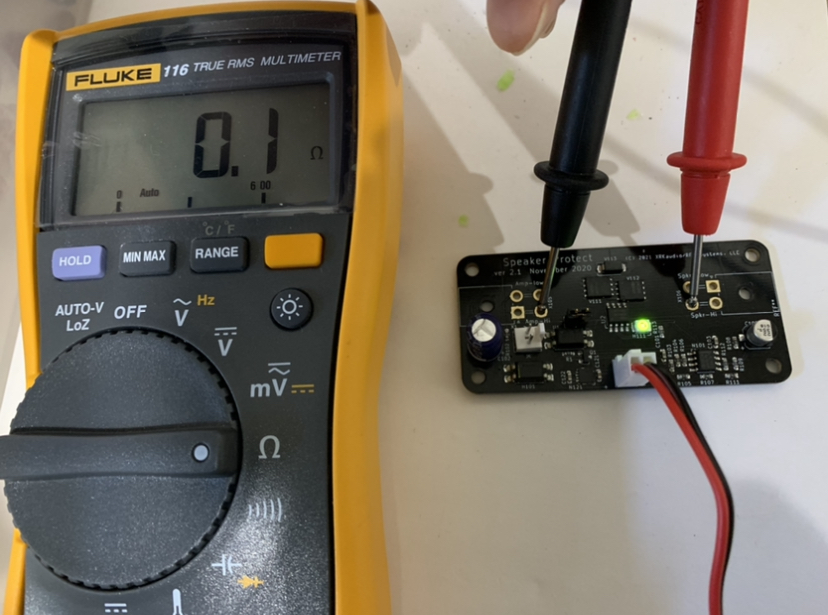
This is how I test each of the SSRs before shipping them.
Testing of SSR Speaker Protection Board - YouTube
Testing of SSR Speaker Protection Board - YouTube
Can you guys please edit the TDA7293 Xmas Amp list and add what I am supposed to ship to you with the free Xmas amp boards?
This will help but it still makes the workflow slow. That’s why I like using the Etsy store to handle this. It presents me with a list to fulfill and makes the associated shipping labels.
Done.
https://www.diyaudio.com/forums/chi...p-dibyas-tda7293-jhofland-27.html#post6510064
Thanks for all your work on this X - IOU a beer (or two)...
- Home
- Group Buys
- Ready-to-Run (RTR) SSR DC Speaker Protection and Delay GB