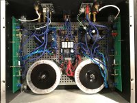
Another happy SSR user here! I installed a pair in my Class A chassis today. It was so quick and easy. Just robbed a little power off of each positive rail and hooked up the positive speaker output through each SSR. That’s it! Worked like a charm on power up. I certainly can’t hear any difference in sound quality, just as X’s measurements show. Thanks for a great speaker protection board everyone!
Attachments
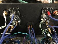
Thanks X. I think you did. I probably left them at the bottom of the envelope in my haste to get them installed. Going to take the amp to my friend’s place for a listening session and don’t want to blow up his speakers. ") I’ll go back and clean things up a little more with the KK connectors. There is another nylon standoff under each board to provide a little more stability for now. Again, I was rushing things a bit and didn’t have time to drill more holes. I just used the holes I had there from my old DiyA speaker protect board. You’re, right though, these little boards don’t need much. They can fit just about anywhere.
I’ll go back and clean things up a little more with the KK connectors. There is another nylon standoff under each board to provide a little more stability for now. Again, I was rushing things a bit and didn’t have time to drill more holes. I just used the holes I had there from my old DiyA speaker protect board. You’re, right though, these little boards don’t need much. They can fit just about anywhere.
I hesitate to call the amp an F7 since NP hasn’t released the official schematic yet, but that’s basically what it is. Based off of Oreo382’s schematic and PCB’s. It uses Exicon lateral mosfets and Toshiba jfets in the front end. Great sounding amp!
I’ll go back and clean things up a little more with the KK connectors. There is another nylon standoff under each board to provide a little more stability for now. Again, I was rushing things a bit and didn’t have time to drill more holes. I just used the holes I had there from my old DiyA speaker protect board. You’re, right though, these little boards don’t need much. They can fit just about anywhere.I hesitate to call the amp an F7 since NP hasn’t released the official schematic yet, but that’s basically what it is. Based off of Oreo382’s schematic and PCB’s. It uses Exicon lateral mosfets and Toshiba jfets in the front end. Great sounding amp!
Ahh, an early reverse engineering adopter. Nice - always wondered what an F7 sounds like. So how does it sound compared to an Alpha?
I reverse engineered a horn speaker based on photos from the manufacturers website once, combined with Akabak modeling. It worked pretty well. Maybe even better than the original.
DIY is fun in that way.
We are now down to 2 last remaining pairs of SSR’s. I guess I will be starting GB #2 soon.
I reverse engineered a horn speaker based on photos from the manufacturers website once, combined with Akabak modeling. It worked pretty well. Maybe even better than the original.
DIY is fun in that way.
We are now down to 2 last remaining pairs of SSR’s. I guess I will be starting GB #2 soon.
I was very curious about it since the circuit seems so simple and I also wanted to see what the lateral mosfet sound was all about. I like it so far. Unfortunately I used the same chassis that my Alpha 20 was in, so I can't A/B them. But, from my memory I can say the bass is probably more pronounced with the F7 vs the Alpha. Sound stage and imaging are also great. Probably on par with the Alpha, but again, hard to tell without having both to compare side by side. I also switched to a dual mono PSU using the Gtose, Prasi, Mark Johnson Cap Multiplier boards. So I'm sure that also affected things...in a really good way.
DIY is a blast, especially with so many talented people creating all of these great components to work with. I can't express my gratitude enough!
Congrats on selling out the SSR's. In the long run it's cheap insurance for our valuable speakers. I may need to get in on GB#2!
DIY is a blast, especially with so many talented people creating all of these great components to work with. I can't express my gratitude enough!
Congrats on selling out the SSR's. In the long run it's cheap insurance for our valuable speakers. I may need to get in on GB#2!
Can we start the second round right away please?One last pair of SSR’s left!
You'll be surprised how many such modules one consumes if one builds multi-way active speakers. Specially with the tweeters directly connected to power amps.
SSR in action.
My USSA5 used to have a slight thump upon switching off, now with SSR installed.
There are no thump when switching the amp on or off.
I feel safe now, as I have experienced a bad incident in the past, my MF amp took out my Tannoy speaker, it caught fire!
Happy Camper!

My USSA5 used to have a slight thump upon switching off, now with SSR installed.
There are no thump when switching the amp on or off.
I feel safe now, as I have experienced a bad incident in the past, my MF amp took out my Tannoy speaker, it caught fire!
Happy Camper!

Hi X,
The package with 4 SSR, 4KK, and 8 crimps arrived safe. Since I have never put a KK connector together:
1. I assume wire is crimped on first.
2. The crimped assembly is inserted in the end of the plastic connector. Does it matter which way it is inserted (ie, crimps facing towards top, bottom, sides, when positioned correctly to slide over the pins on the pcb)?.
3. Pins on the soldered connector only have to touch the crimped end to complete the circuit.
4. Any thing I have missed?
Thanks for the help
Regards
To crimp it properly, a $20 crimp tool is a must. Trust me you will use it often and wonder how you got along without one before. It’s the ideal way to run low current low voltage signal lines or low power lines between components. If you are in a rush, don’t want to deal with it, just solder your power wires on the terminals or the proper holes/pads on the board.
Regarding orientation, once crimped, the wings that bite into the wire form a flat that faces up towards the protrusion. If you look at the cross section of the crimp ferrule you will see there is almost a trapezoid shape. Match the trapezoid and push into the shell until it clicks and locks.
IZOKEE Crimping Tools Ratcheting Crimper Plier for Terminals Pins AWG28-16 0.1-1.5mm² PH 2,0mm/XH 2,54mm/Dupont 2,54mm/TAB 3,96mm/KF2510/JST Wire Connectors https://www.amazon.com/dp/B0793T3L2D/ref=cm_sw_r_cp_api_i_y4x8DbJ31CKC0
Nice video:
YouTube
- Home
- Group Buys
- Ready-to-Run (RTR) SSR DC Speaker Protection and Delay GB