Hi
This protection could be good for a circlotron ?
https://circlotron.audio/sites/default/files/inline-images/20190613_J113_TTA_0.png
This protection could be good for a circlotron ?
https://circlotron.audio/sites/default/files/inline-images/20190613_J113_TTA_0.png
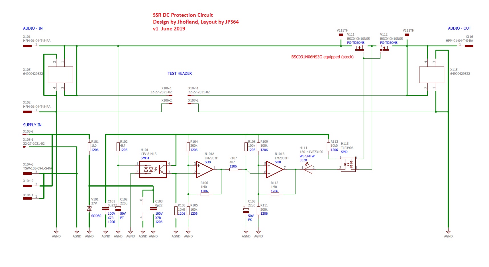
I don’t understand your circuit as the speaker is placed between two -35v rails of two power supplies, and the outputs drive those connections.
The Gen2 SSR is designed to withstand global DC offsets like that in a BTL amp since the speaker input and outputs are optically isolated from the power supply and are “floating” relative to PSU ground. So a BTL amp that would have Vcc/2 at the outputs all the time could work. The DC is detected relative to the two speaker output terminals. So in this case it will have to go after the node where the two PSU negative rails and output stages connect. Basically right before the output binding posts (like in most amps). But, yes, it should work.
The Gen2 SSR is designed to withstand global DC offsets like that in a BTL amp since the speaker input and outputs are optically isolated from the power supply and are “floating” relative to PSU ground. So a BTL amp that would have Vcc/2 at the outputs all the time could work. The DC is detected relative to the two speaker output terminals. So in this case it will have to go after the node where the two PSU negative rails and output stages connect. Basically right before the output binding posts (like in most amps). But, yes, it should work.
Hey, X.
In theory, If I wanted to extend the delay of the gen 1 SSR to 30 seconds or so, what value would I need for R8?
Honestly, I probably wouldn’t be able to change those resistors, anyway...
In theory, If I wanted to extend the delay of the gen 1 SSR to 30 seconds or so, what value would I need for R8?
There is a 2-3 second turn on delay that should help to avoid turn on thump. If you need a longer delay, one of the RC time constant components (R108 or C108) can be made larger. Generally, the resistor is the easier one to change. Presently, R108 is at 100k.
Honestly, I probably wouldn’t be able to change those resistors, anyway...
Once it trips, it takes 2 seconds to come back on after the DC is removed. I think the timer is based on a 100k and 22uF cap. R108 and C108.
I don’t think it’s practical to make it 30 seconds as that might not be very accurate or stable. If 2 seconds is 100k, 15x longer is 100k x 15 or 1.5Mohm.
I don’t think it’s practical to make it 30 seconds as that might not be very accurate or stable. If 2 seconds is 100k, 15x longer is 100k x 15 or 1.5Mohm.
Last edited:
Hi x, just to let you know that I ordered 3x Gen2 SSR boards from your Etsy shop on Friday. Forgot to note my DIYA screen name on the order.
With the bonus quick shutoff boards these are just what I'm looking for. Never did find a way to get the Gen 1 boards to shut off quickly enough to catch turn off thump!
With the bonus quick shutoff boards these are just what I'm looking for. Never did find a way to get the Gen 1 boards to shut off quickly enough to catch turn off thump!
Never did find a way to get the Gen 1 boards to shut off quickly enough to catch turn off thump!
Did you try the 1/2bridge and 10uF cap low capacitance power supply to power the SSR to shut it down? This is discussed a few pages earlier. Works really well for me.
I don’t think it’s practical to make it 30 seconds as that might not be very accurate or stable. If 2 seconds is 100k, 15x longer is 100k x 15 or 1.5Mohm.
Understood. Thanks.
Did you try the 1/2bridge and 10uF cap low capacitance power supply to power the SSR to shut it down? This is discussed a few pages earlier. Works really well for me.
Oooh interesting! I didn't spot that. It's been about a year since I was experimenting with solutions to this.
I'm guessing a bridge rectifier would be ok? I have some here somewhere but no individual diodes. Should be able to find a resistor and a cap..
Hi Folks,
An update on the shipping progress of the Gen2 SSR's. I had about half of them packed and ready to ship and was looking at the board again and realized that the bolt mounting holes do not have the proper isolation from the ground plane pours. That is, if you use a metal standoff, the board ground will possibly contact your chassis ground as the solder mask is the only thing stopping it. You could add a piece of Kapton tape over the hole to help insulate the board, but the holes are somewhat plated through (some are and some aren't). This may or may not result in a ground loop. This was something I failed to catch prior to production and will be fixed in the next batch. However, to remedy this, I will provide a set of 4 nylon M3 standoffs (male/female hexagonal body type) for each unit at no charge to alleviate this potential ground loop problem. Sorry for the inconvenience and hope that this is an OK solution.
This means that I will need to wait for the standoffs to arrive and repackage the shipments to include the standoffs. Probably won't send out until this Friday or Saturday. As a bonus to make up for the error, I will throw in a pair of OnSemi BC546 transistors so that you are off to a headstart on making the instant-off shutdown controller board. All you need are a few resistors, some basic 1n400x diodes, and a small 4.7uF cap that many of you will have in your bench parts bin.
Thanks for your understanding.
Last edited:
You know what they say, X, no good deed shall go unpunished! 
Seriously though, no problem at all, and thanks so much for going out of your way to correct it, especially with all your other current shipping headaches with the Xmas amp. I appreciate all you contribute to the DIYA community.
Seriously though, no problem at all, and thanks so much for going out of your way to correct it, especially with all your other current shipping headaches with the Xmas amp. I appreciate all you contribute to the DIYA community.
Well I appreciate the support, folks and glad that you feel this is a suitable solution.
The Gen2 SSR is otherwise, a superb little board that works well and handy to have in many projects.
Jhofland has tested out the bonus instant off board. But I should try it myself soon.
The Gen2 SSR is otherwise, a superb little board that works well and handy to have in many projects.
Jhofland has tested out the bonus instant off board. But I should try it myself soon.
- Home
- Group Buys
- Ready-to-Run (RTR) SSR DC Speaker Protection and Delay GB