I was just getting ready to start my SLB build when I saw your post. Thank you. I was thinking there was something wrong with me. My brain was really struggling to decode those J5-J7,J6-J14 pictograms.😱😱😱
And thanks to X for explaining the real way to figure it out.
Don
Glad my confusion helped you Don.

Congrats on your sleuthing JT!
Nice work. That was a hard one and could happen to anyone. The worst ones are when your probe leads or OScope leads are damaged and internally shorted (sometimes). That kicked my @$$ for a week once on a project pulling my hair out. 🙁

Nice work. That was a hard one and could happen to anyone. The worst ones are when your probe leads or OScope leads are damaged and internally shorted (sometimes). That kicked my @$$ for a week once on a project pulling my hair out. 🙁
Thanks brother... I feel good about this one. I'm glad I took the time, swallowed the frustration and worked it out.
I just finished it and zeroed the offset. I want to make safety chage to the first mono I built. I have the leads bending around the board in and L shape to the sink. After I had that lead short with the prob... I realized the way I have the BJTs mounted is less than ideal and in fact dangerous. I will be placing ceramic where it could make contact to prevent the possibility of a nasty short.
Build and learn!
JT
Hello.
Did I understand correctly that for separate ACA amp power supply, I need 2 mono PSB and 19v transformer.
I am currently using :
2x18 160va (~ 4.5a per channel) => bridge rectifier => 10000uf => choke 10h (159zj) => 10000uf
After assembling, I realized that it takes up quite a lot of space, and now I came across this topic. This seems like a great solution.
Replacing the transformer is not a problem.
If you want mono blocks then two single rail SLBs will work. It can handle 5A each so you could run one SLB for both channels if you wanted.
ACA is nominally 19v to 24v (v2). Here is how to estimate trafo needed. Work backwards starting with say 24v. Assume 3v drop in cap Mx. Assume 3-4v sag in trafo if using Antek. So add 7v to 24v we get 31v. Divide by 1.41 and we get 22vac trafo. Size power rating assuming load is nominally 1/3rd of rated power. ACA is 1.25A current x 24v or 30w. You also have some losses in cap Mx with 1.25A x 3v or about 4W. So 3x 34w is about 100w so 100VA trafo should do it. But 100VA trafo sags too much under 1.25A. So go next one up at 200VA.
I would get 22V 200VA Antek per channel or 22V 400VA for stereo.
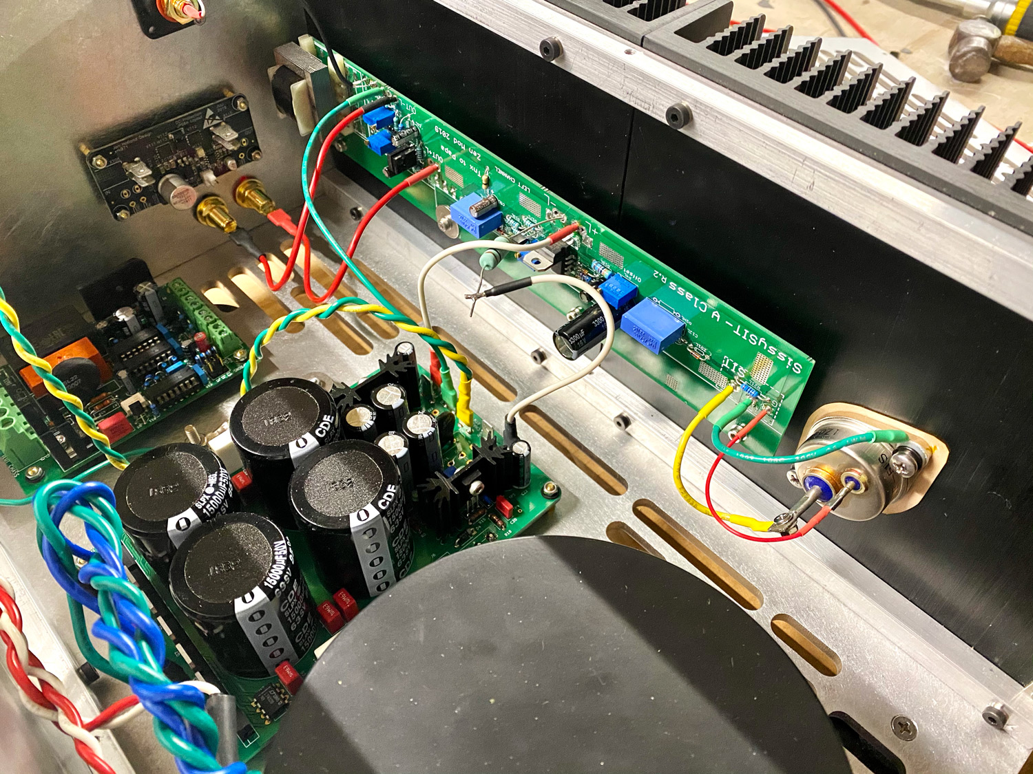
I recently built up Zen Mod's SissySIT as monoblocks, used SLB for a little something different after several amps with the DIY store PSU (which is great, but physically large)...Put in my own Quasi snubber values (56R).
With Antek 2222 I got +/-30.5V unloaded rails. Loaded with one amp board (monoblocks) they settled around +/-27V... current draw on the the SissySIT higher than typical Pass designs, 1A8.
😀 Playing music on the test speaks—letting them heat up! 😀
Post #1791
Babelfish M25, SissySIT - general building tips and tricks
Very nice work Pfarrell!
I see you have a RTR SSR in there too. If you ever need a matching soft start there is the SFP.
I see you have a RTR SSR in there too. If you ever need a matching soft start there is the SFP.
Ha! Thanks. i built some VERY nice speakers...and think it's prudent to safeguard them—woofers anyway. Just need to run some power—V+ on the left pin? Wasn't sure actually. And need to refresh my memory on speak connections, top is Pos?
SissySIT sounds sweet.
SissySIT sounds sweet.
There is a new development on the RTR SSR, you can have them shut down instantly when power switch it thrown off to prevent turn off thump (if that was an issue).
Ready-to-Run (RTR) SSR DC Speaker Protection and Delay GB
The pins are described in the schematic:
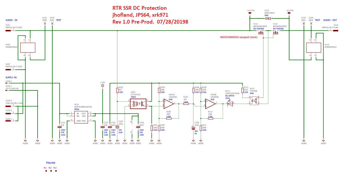
Use a continuity meter to see which one is pass through ground for speaker connects. Also use it to see which pin on power input is GND or +V.
Ready-to-Run (RTR) SSR DC Speaker Protection and Delay GB
The pins are described in the schematic:
Use a continuity meter to see which one is pass through ground for speaker connects. Also use it to see which pin on power input is GND or +V.
Why can't I understand transformers
I finished my first SLB build, except for the flying leads, and was reviewing the circuit diagram in preparation for power on and test. Something I do for each piece in a box so I don't make one problem another problem. J2 is AC in 1 which leads to PVout in the circuit diagram. I am using the SLB in an M2X mono amp with an Antek AS-3220.
The Anteks Always are labeled with a diagram showing Blue-Green, Blue-Green output. In this case with a 20V marking. Since Blue is opposite Red (input) I always take this as the higher voltage in the pair. But in numerous fotos, people are wiring blue to J1 which goes to Ground out not to VPos. Why doesn't blue go to J2 which leads to VPos out?
What am I missing?
Thanks,
Don
Wow, 400VA for such a small amplifier is quite impressive. In EU, it's easier for me to order a transformer from Toroidy. It seems to me that two windings of 22v at 300va will be ok if follow your calculations.
Thank you.
Thank you.
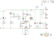
AndyR posted in another thread that he is having intermittent problems with R18 frying. All I can suspect is that there is a loose connection on the BJT pass-transistor.
Hi X. You posted (in the other thread):
"Hi Andy,
When you have a loose connection on the BJT the current passes through both R15 and R18, and either may burn out. Have you verified that you don’t have a cold solder joint on the board somewhere? The PCB has a large ground plane and being 2oz copper and 2mm thick FRP, requires at least a 60w iron and big fat chisel tip to fully liquify the solder. Cold solder joint might cause intermittent connection leading to random melt downs. That’s about all I can think might be the problem as no one else seems to be having these issues. What value are you using for R18? ".
R18 is 10 ohm, X. And, on Hugh's advice:
* C25 has been increased to 220pF.
* and I now have a 220pF ceramic between Collector & Base of Q12.
Yes, no-one else has had this problem ... but then, no-one else has built 4R ANs!
The really peculiar thing is that I do 3 tests when making a change to the SLB (like, replacing a blown R18!):
1. SLB by itself - not loaded.
2. SLB loaded on the +ve DC rail and the -ve DC rail with a 60w, 6.66 ohm dummy load that I made up from a collection of 10w, 10 ohm ceramic resistors (to draw a 3.2a current from each 21v DC rail).
3. SLB with AN board connected.
#1 & #2 work fine:
* R18 doesn't smoke, and
* R4/R6 only get slightly warm in the case of #2 (they are cold in the case of #1).
Test #2 suggests to me that my soldering must be OK?
But when I connect up the AN board ... R18 starts to smoke - and R4/R6 get very hot! 🙁
Hence Hugh is thinking that maybe the AN 4R circuit is not compensated correctly and is oscillating. So I am waiting for my Variac to arrive, so I can reduce the input mains voltage to get +/-15v on the SLB DC rails. If R18 doesn't smoke ... then AN oscillation would seem to be the cause of R18 on the SLB smoking at full voltage!
Andy
Last edited:
Keep us in the loop on this one Andy... a 4ohm has been considered for a pair, so it would be nice to know going in.
JT
JT
Keep us in the loop on this one Andy... a 4ohm has been considered for a pair, so it would be nice to know going in.
JT
Sure, JT ... but no further progress until my Variac arrives - which might not be till the end of next week. 😡 (I could've walked into a shop and picked one up but Amazon Oz had exactly the same item for 20% less.)
Andy
But when I connect up the AN board ... R18 starts to smoke - and R4/R6 get very hot!
Can you clarify: R4/R6 on Alpha Nirvana get hot when amp is connected?
Why are you looking at 6.7 ohm load and then connecting a 4ohm load? I'm just trying to get my mind around this thing...
Last edited:
- Home
- Group Buys
- The SLB (Smooth Like Butter) Active Rect/CRC/Cap Mx Class A Power Supply GB