
I take it you are using 2sk170 - did you test them / measure idss?
When you say the voltage is fluctuating, what kind of readings are you getting?
What voltage are you getting each side of R4 with respect to ground? (should be 22v ish and 9v).
Is there any contact with the component tails and the chassis? Move the board up a level temporarily while you test.
Do you get any activity in the tube?
Your build looks fine, I can't see anything obviously amiss when comparing it to my build photos.
Yes Toshibas with idss of 6.4 matched.
No steady voltage readings the p/s fluctuates from 2/3 volts to my DMM saying overload which I assume it is unable to lock onto a voltage range.
I cannot see anything being in contact with the chassis and initial check was done out of the chassis.
No glow from the valve.
No steady voltage readings the p/s fluctuates from 2/3 volts to my DMM saying overload which I assume it is unable to lock onto a voltage range.
I cannot see anything being in contact with the chassis and initial check was done out of the chassis.
No glow from the valve.
I'm struggling to find a set of matched 2sk170s. I've tried a couple of people on DIYAudio but have not managed to get hold of a set.
Where are people looking to get a set of 2sk170s?
Ta.
Verified seller on ebay:
Toshiba 2SK170 LAB MATCHED OCTET to 0.03mA / 4mV (8 matched FETs -- 7mA range) | eBay
Expensive, but punkydawgs has been a reliable supplier for many of us here.
Hi ppap64. Yes if there is some interest I can place a small batch order in a few weeks. I'll order some other PCB and I can order this one as well. The new batch will have a new design for the AC input, with larger spacing between the AC lines, as requested originaly and the small pcb error is corrected.
Anyone interested let me know.
To participate with the current discussion I used K170-GR grade for my JFET. The values I had were around 4.5-4.8ma. These -GR JFET were left over from my ONO phono preamp that I made years ago... I don,t think you need a match octet, matched quad for the first section, and then an other matched quad is sufficent. A matched quad may be less expensive. Also there is a few vendors of 2SK370-GR out there, that can be used.
My PCB, as the Chritsmas Gift edition NP did, supports J113 JFET. Just order them from Mouser, add a source resistor to degenerate the transconductance, and adjust the resistor to get into the 4-5ma IDSS range. It should also work.
Don't forget that these JFET are used has buffer (with a CCS current source), with an unity gain. Most, if not all the 'sound' and gain is coming from the Kord tube. Hence the JFET are not that critical, they are there mainly to insulate the KORG tube from the Input/Output...
SB
Last edited:
I'm struggling to find a set of matched 2sk170s. I've tried a couple of people on DIYAudio but have not managed to get hold of a set.
Where are people looking to get a set of 2sk170s?
Ta.
I bought a bag of 50 from UTSource on ebay and matched them myself. They were advertised as 6mA IDSS but 90% were between 2.7-5.7. That said, they seem to be genuine and I managed to match enough of them within 1mA.
I took a gamble for $8 delivered knowing that most of the Jfets would be unusable for the project, maybe non-genuine and also knowing that many others have had bad experience getting parts from UTSource.
You can always get them prematched from the DIYA Store Linear Systems LSK170 Ultra Low Noise Single N-Channel JFET (8 Pieces) – diyAudio Store.
Yes Toshibas with idss of 6.4 matched.
No steady voltage readings the p/s fluctuates from 2/3 volts to my DMM saying overload which I assume it is unable to lock onto a voltage range.
I cannot see anything being in contact with the chassis and initial check was done out of the chassis.
No glow from the valve.
I'm thinking you have a short or low resistance path somewhere that is pulling the PSU into protection. I had the same behaviour when I pulled too much current via the LED resistor.
If you are comfortable with desoldering components, I'd pull the zener diodes and bench check those are breaking down at 9v.
With those back in, I'd pull one leg each of R103 and R107 to disconnect +F from the circuit and see if the heater +R side of the circuit works.
If so, then I would move on to the FETs to make sure they function.
Whoops  . Staring at the back of the board I realised that I had soldered the wire link between C202 and R209 and R208 at the wrong end of the two resistors. What damage and to what am I likely to have caused bearing in mind that the voltage will still not settle. On the up side the led I installed actually glows.
. Staring at the back of the board I realised that I had soldered the wire link between C202 and R209 and R208 at the wrong end of the two resistors. What damage and to what am I likely to have caused bearing in mind that the voltage will still not settle. On the up side the led I installed actually glows.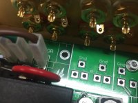
That would short out the RH channel output to ground via the negative side of C202.
Check Q202, Q203 for damage for a start. You should be ok to remove those two and switch on to check voltages.
Thanks avtech.
I removed Q202/3 and both check out ok still reading 6.77mv idss. Powered up I am still having the same problem with the p/s fluctuating although it does now slowly rise.
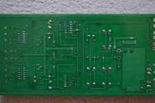
Unfortunately it doesn't reach 24V . I only let it get to 12.5V before turn off but it took a couple of minutes. I made a mess of the back panel s0 made one out of 3mm acrylic which is why there is an earth wire soldered underneathnready to attach to the chassis base. A bottom view. I much appreciate the help.

Attachments
Last edited:
- Home
- Group Buys
- GB B1 Nutube PCB with integrated PS