Yes I had unsoldered it as SB mentioned in his build notes that voltages could be checked without the Nutube in place. Sorry should have said.
...I'd pull one leg each of R103 and R107 to disconnect +F from the circuit and see if the heater +R side of the circuit works.
What was your result for this one? Did you get stable 9V?
That's actually a good thing as we have isolated most of the circuit.
Remove R203 and 207 also if you didn't already and check for the 9v at R4 (+R).
Then if still no stable power supply, remove R4 and look for 23v/22v on R3 (WRT GND).
If it is stable, then the fault is between R4 and the LED.
If not stable, the fault is further back so remove R3 and look for 23.4/22.8v on R2 (WRT GND).
Make sure you have a printed schematic (the V1.3) and mark off what you find as you go.
You'll get there soon!
Last edited:
Finally got around to finishing the PC board and had to quickly give it a test run before installing it into a case. Powered right up perfectly. Set bias to 10V and I'm now listening to wonderful music.
Thank you Sylvain for designing this unique board and for the group buy. Thank you JeffreyJuice for the JFETs. And finally, thank you Nelson for sharing your exceptional creations with the DIY Greedy Boyz.
Thank you Sylvain for designing this unique board and for the group buy. Thank you JeffreyJuice for the JFETs. And finally, thank you Nelson for sharing your exceptional creations with the DIY Greedy Boyz.
Attachments
![IMG_2792[574].jpg](/community/data/attachments/687/687935-325dd2fc4a6a365bd09ad0356b48d0cb.jpg?hash=Ml3S_EpqNl)
With R103/203 and R107/207 removed I have stable voltages of +24 with 9.4V at R4; to high? When I solder back in R103/7 things become unstable but there is 9.18V at R4 and the diodes.
Please confirm your results for the following:
R103 & R107 removed, R203 & R207 connected:
R103 & R107 Connected, R203 & R207 removed:
9.4v is a touch high:
Best to match the Zeners to 9.1v if possible. I tested a batch of 10 zeners and chose the pair closest matching 9.1v.
R103 & R107 removed, R203 & R207 connected:
R103 & R107 Connected, R203 & R207 removed:
9.4v is a touch high:
...Also, the tolerance here on the zener is about 9.0 to 9.2V
If you are not within that, consider adjusting the resistors in series with the Cathodes.
Best to match the Zeners to 9.1v if possible. I tested a batch of 10 zeners and chose the pair closest matching 9.1v.
With R103/R107 I have 9.18V at the diodes all other voltages fluctuate.
With R203/R207 I have 8.5V at the diodes all other voltages fluctuate but are 3V down.
I have ordered more 1N4739A diodes and will rig up a test circuit.
With R203/R207 I have 8.5V at the diodes all other voltages fluctuate but are 3V down.
I have ordered more 1N4739A diodes and will rig up a test circuit.
If you have a voltage drop with R203/207 connected, it suggests an issue on the #2 side of the circuit.
With just R203/207 connected and getting the voltage drop at the 24V, take R4 out of the circuit and see if the 24V stabilises.
With just R203/207 connected and getting the voltage drop at the 24V, take R4 out of the circuit and see if the 24V stabilises.
Thanks I will check that today. The diodes arrived yesterday so I will hopefully be able to find some that are closer to 9.1V than those I have at the moment.
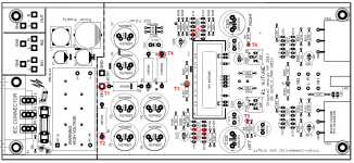
Hi all. I was wondering what the equivalent test locations are for measuring the voltages T1 to T8 described in the original Firstwatt article ?
If you have a voltage drop with R203/207 connected, it suggests an issue on the #2 side of the circuit.
With just R203/207 connected and getting the voltage drop at the 24V, take R4 out of the circuit and see if the 24V stabilises.
With things as you suggested the voltage fluctuates but settles at 24.04V and the LED lights up.
With things as you suggested the voltage fluctuates but settles at 24.04V and the LED lights up.
I forgot to say it takes 30 seconds to finally settle at 24.04 volts.
With R203/R207 I have 8.5V at the diodes all other voltages fluctuate but are 3V down.
You meant with R203/R207 removed, R103, R107 connected? Sorry, I misread your post.
With things as you suggested the voltage fluctuates but settles at 24.04V and the LED lights up.
This suggests an issue on the #1 side of the circuit as you get a settled voltage with the left side (R103/7) out of circuit. Mine takes a while to settle also, presumably as the triode warms up.
This time with just R103/107 connected (R203/7 out) and getting the reported 3V drop at the 24V, take R4 out of the circuit and see if the 24V stabilises (R4 will cut the 9V side of the circuit). This should tell you if it is heater side or buffer side.
If no change, put R4 back in, take R103 or R107 out of circuit. This will then hopefully identify if it is the input or output side of the tube that is the problem.
I can't remember if I asked, but where did you source your JFETs from?
Sorry I should have said the readings are without the Nutube in place. I will try what you suggest. Should I solder the tube back in place?
The jfets were sourced from Spencer of Fet Audio some years ago and matched by me. Your advice is much appreciated.
The jfets were sourced from Spencer of Fet Audio some years ago and matched by me. Your advice is much appreciated.
Last edited:
- Home
- Group Buys
- GB B1 Nutube PCB with integrated PS