This group buy is for PCBs for a fixed frequency passive notch filter designed by Samuel Groner for very high resolution distortion measurements.
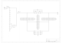
The schematic, together with construction and application notes, can be found on Mr. Groner's web site. A copy of the schematic is also attached below.
In terms of the price, it is $10 apiece plus the cost of USPS First Class shipping and an envelope (together, about $4 for the US and $15 elsewhere).
This GB has been agreed upon with Mr. Groner.
If you're interested, please post your name and the quantity of the PCBs desired.
BTW, I have designed a little PCB for a fixed frequency passive notch filter for very high resolution distortion measurements. The exact notch frequency is tuned to a fixed value during construction by iteratively adding selected resistor values. The easily implemented frequency range is about 10 Hz to 20 kHz (I've gone up to 100 kHz, but the notch depth degraded presumably because of strays) and set by chosing suitable capacitor values. As an additional feature it includes a selectable 10/20 dB input attenuator. This allows measurement verification at lower notch filter operating levels to gain further confidence in the measurement result.
This design is not as easily used as implementations which include notch filter bootstrapping (to avoid significant attenuation of the 2nd and 3rd harmonic; for my design you'll need to correct for frequency response) and center frequency trimming (for my design you'll need to adjust the oscillator frequency if it doesn't match the notch frequency). However, it avoids the subtle and difficult to quantify distortion contributions from the bootstrapping opamps and potentiometers and is thus more suitable when working below -120 dB.
I'm still evaluating this design with respect to its distortion contribution, but it looks like it is below -130 dB.
The schematic, together with construction and application notes, can be found on Mr. Groner's web site. A copy of the schematic is also attached below.
- Resistors are metal/thin film MiniMELF (R11-R14, R18 and R19 0.1%, others 1%).
- Caps are ceramic C0G, 1206, 1%, 50 V or higher.
- Shown capacitor values are for 10 Hz. 10 nF gives 100 Hz etc.
- R15-R17 and R20-R23 are selected to tune the exact notch frequency.
In terms of the price, it is $10 apiece plus the cost of USPS First Class shipping and an envelope (together, about $4 for the US and $15 elsewhere).
This GB has been agreed upon with Mr. Groner.
If you're interested, please post your name and the quantity of the PCBs desired.
Attachments
Last edited:
Hi Alex,
I can see these will need a whole mess of soldering to build!
Tentative for 3 PCBs
-Chris
I can see these will need a whole mess of soldering to build!
Tentative for 3 PCBs
-Chris
Thank you gentlemen for joining!
Soldering 1206 is not that bad imho. Tuning the notch by selecting resistors may be more involved.
Hi Alex,
I can see these will need a whole mess of soldering to build!
Tentative for 3 PCBs
-Chris
Soldering 1206 is not that bad imho. Tuning the notch by selecting resistors may be more involved.
Please add me in
Hi Alex
please will you add me in for 2 boards
I am in the UK
Thanks
Fredbloggstwo
Hi Alex
please will you add me in for 2 boards
I am in the UK
Thanks
Fredbloggstwo
Last edited:
Confirming the above.Soldering 1206 is not that bad imho. Tuning the notch by selecting resistors may be more involved.
I've built two filters based on this design and PCBs - one with a fixed notch frequency, and one variable.
Some info, including the publications on the Hall topology the filter uses, can be found here:
http://www.diyaudio.com/forums/equi...n-audio-range-oscillator-534.html#post4880228
The tuning is involved, but not impossible. I found the paper by Kenneth Kuhn (referred to in the above link) useful in this regard.
Well tuned, the filter is capable of at least -100dB attenuation at the notch frequency.
Regards,
Braca
I'd love 2 pcb's, please. Thanks for opening this up for us!
(Edited for conciseness of language)
(Edited for conciseness of language)
Last edited:
I have a question after looking at the schematic. I should have asked when he first posted. Should the resistors in the filter be in a series/parallel network to reduce the signal across them? Same for the caps? I believe there is a direct relationship between the signal level and nonlinearity.
I believe it would be best to direct technical questions regarding the filters, etc. to Samuel Groner - apologies for deflecting your question. He promised to be available for technical matters.I have a question after looking at the schematic. I should have asked when he first posted. Should the resistors in the filter be in a series/parallel network to reduce the signal across them? Same for the caps? I believe there is a direct relationship between the signal level and nonlinearity.
sign me up for 4 of these barren units 🙂
Cheers
Alan
PS I seem to recall that he had that (series - parallel) as part of his design when he first published that topology, but I could be wrong. Not a bad idea, but would certainly complicate some of the tuning.
Cheers
Alan
PS I seem to recall that he had that (series - parallel) as part of his design when he first published that topology, but I could be wrong. Not a bad idea, but would certainly complicate some of the tuning.
Last edited:
Alan, let me know if you want to go in together on parts to get into bulk discounts. I think I owe you a hello regardless. 🙂
I am slow to remember things, I had Samuel email me a copy of the file years ago and didn't actually get them made at the time. I recall looking at the BOM and some of the switches/connectors were EOL back then (2years or so ago). Have these been checked for equivalent parts or gerbers updated?
- Home
- Group Buys
- PCB for Samuel Groner's low distortion passive notch filter