Samuel recommended MiniMelf resistors, and preferred them to thin film 1206. Sometimes I was forced to use the latter ones, due to some values not being available as MiniMelf.
Irrespective of the type, resistors in the filter should preferably have a tempco of 25ppm/K, for those in the attenuator 50ppm/K is ok.
Irrespective of the type, resistors in the filter should preferably have a tempco of 25ppm/K, for those in the attenuator 50ppm/K is ok.
Ok, here are the capacitor data.
The filter I'm currently using has a nominal notch frequency of 1kHz and is based on a capacitance of 100nF. Each leg is composed of ten 1206 ceramic NP0/C0G capacitors, nine of which have a capacity of 10nF, and the tenth one is trimmed such that each leg has nearly the same capacity.
I bought 50 capacitors (TDK CGA5L4C0G2J103J160AA) with a tolerance of 5% (1% caps are very expensive), measured the capacity of each of them and made three groups. The first group has ten caps and the other two nine caps each and must be trimmed such that their respective capacities are as close as possible to the first group value. This is achieved by finding a combination of the tenth capacitor and one of two smaller caps soldered "piggy back" onto the other ones.
The exact value of the capacitance is not important, but the matching of the three legs is critical: a deviation of 0,5% in a single leg reduces the notch depth by 30dB or more (my build achieves a notch depth of at least -100dB).
I hope the above description makes some sense.
Regards,
Braca
Since you used 10nF each for 1kHz you must have reduced the resistors to one tenth the value on Samuel's schematic, correct? If that is correct did you do that to reduce insertion loss outside of the notch region or for another reason?
Yes, by going from 10nF to 100nF, the resistances changed by the same factor.
The reason for reducing the resistances in the filter was noise: as per LtSpice, filter with 10nF has in the freq. interval 10Hz-20kHz an integrated noise of 1.04uV, whereas the one with 100nF has 332nV, i.e. 10dB less.
In comparison with the input noise of Groner's LNA (0.39nV/rtHz), filter noise clearly dominates, and the net noise floor reduction at the LNA output is thus 9.8dB.
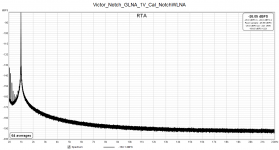
Enclosed is a THD measurement of the Victor's oscillator at 1Vrms, followed by my 100nF Hall filter and Groner's LNA.
Regards,
Braca
The reason for reducing the resistances in the filter was noise: as per LtSpice, filter with 10nF has in the freq. interval 10Hz-20kHz an integrated noise of 1.04uV, whereas the one with 100nF has 332nV, i.e. 10dB less.
In comparison with the input noise of Groner's LNA (0.39nV/rtHz), filter noise clearly dominates, and the net noise floor reduction at the LNA output is thus 9.8dB.
Enclosed is a THD measurement of the Victor's oscillator at 1Vrms, followed by my 100nF Hall filter and Groner's LNA.
Regards,
Braca
Attachments
Is there enough interest to buy another round of PCB's? If so I would be in for three or four.
Cheers,
David
Cheers,
David
the gerber file is available on Samuel's site and linked to earlier. You can get 5 boards for a min of $6 USD, or slightly more for slightly higher quality boards. So feel free to do a personal group buy, it ain't much. not like the old days.
Cheers
Alan
Cheers
Alan