lateral fet gate capacitance
From Rod Elliot's Project101:
He uses the same Lateral FETs as are in this amp. This amp adds 47 pf to each FET either side, whereas Rod's only adds capacitance to the N-Channel FETs. Have you tried this sort of asymmetric capacitance balancing in practice or simulation? Do you think the instability he's talking about is only an issue for an LTP VFA amp?
From Rod Elliot's Project101:
The additional capacitors (C11 and C12) shown are to balance the gate capacitance. The P-Channel MOSFETs have significantly higher gate capacitance than their N-Channel counterparts, and the caps ensure that the two sides of the amp are roughly equal. Without these caps, the amp will almost always be unstable.
He uses the same Lateral FETs as are in this amp. This amp adds 47 pf to each FET either side, whereas Rod's only adds capacitance to the N-Channel FETs. Have you tried this sort of asymmetric capacitance balancing in practice or simulation? Do you think the instability he's talking about is only an issue for an LTP VFA amp?
From Rod Elliot's Project101:
He uses the same Lateral FETs as are in this amp. This amp adds 47 pf to each FET either side, whereas Rod's only adds capacitance to the N-Channel FETs. Have you tried this sort of asymmetric capacitance balancing in practice or simulation? Do you think the instability he's talking about is only an issue for an LTP VFA amp?
Yes I have tried. Didn't work.
The issue isn't VFA/CFA. Layout dictates which form of compensation needs to be applied in designs comprising fast devices. P101 uses large caps between gate-source whereas V4H uses small caps between drain-gate. In V4H's layout balancing Cgs mattered much less than balancing Cgd.
Since this mod of balancing Cgd (Rev1) was added, I have not been able to push the amp into oscillation ever again, whereas with P101-like Cgs balancing oscillation was triggered at arbitrary output voltage level and sometimes without any input (and the amp as a whole became slower in bandwidth and slew rate), even doubling the Cdom didn't help stop the oscillation. Solution was to put well defined capacitive loads to the VAS, to both rails and to ground - you can see that there are also two 47pF from VAS output to ground. One would expect this plethora of capacitors put at VAS output must slow it down. But instead, slew rate climbed from 70V/uS to 100V/uS, and I was able to run it fully stably with less than 100R gate resistors.
Last edited:
Hi !
I just had it play full blast (input 0dB) for an 45 minutes this morning, as a test in real life, on one of my big 3 way B&W speaker: really very very good for music and voice.
The heatsink is getting quite hot, nothing actually worrying, will be cooler when mounted on the enclosure's side (Hifi2000 dissipante, Cresnet unregulated +/-50V 600VA SMPS & BeQuiet fans inside).
Thanks to Shaan for his help and patience !
Now going to perform some delicate surgery on my other damaged board.
Cheers
JM
Hi !
Good news again, my 2nd amplifier board (that was seriously overloaded) is finally fixed and working like a charm.
I changed every semiconductor, had to solder some bjt legs directly on the tracks, it's not so nice looking but it's working fine.
")
JM
Do some distortion measurements. If you're not totally set up for high-end measurements, do something quick and dirty. If not at full power, do it at 5W or 10W power. This kind of repair and refurbishing usually needs at least a minimal distortion measurement to verify that there's no major problem anywhere. The difference between 0.5% THD and 0.005% THD is best detected by measurement, and if it's the former, you know something still needs fixing.Hi !
Good news again, my 2nd amplifier board (that was seriously overloaded) is finally fixed and working like a charm.
I changed every semiconductor, had to solder some bjt legs directly on the tracks, it's not so nice looking but it's working fine.
JM
Do some distortion measurements. If you're not totally set up for high-end measurements, do something quick and dirty. If not at full power, do it at 5W or 10W power. This kind of repair and refurbishing usually needs at least a minimal distortion measurement to verify that there's no major problem anywhere. The difference between 0.5% THD and 0.005% THD is best detected by measurement, and if it's the former, you know something still needs fixing.
Thanks. I just did the VAS biasing, offset trimming and mosfet biasing as prescribed for a new setup, without any problem.
Everything stable and good values.
Now I also have a scope (2 channel digital and a signal generator), maybe look what square and sine waves look like ?
JM
Ya, you're right, seeing the waveforms comes first. Distortion measurements after. In my book too.Now I also have a scope (2 channel digital and a signal generator), maybe look what square and sine waves look like ?
Ya, you're right, seeing the waveforms comes first. Distortion measurements after. In my book too.
OK, I'm going to do this.
But I've been playing music quite loud with my best (3 way floorstanding, difficult to drive speakers) without any problem.
JM
Thanks. I just did the VAS biasing, offset trimming and mosfet biasing as prescribed for a new setup, without any problem.
Everything stable and good values.
Now I also have a scope (2 channel digital and a signal generator), maybe look what square and sine waves look like ?
JM
Hi.
Glad to know they're both running.
Don't increase squarewave output beyond 5-10VPP or else the zobel resistors will overheat. If you plan to test the sinewave into clipping then don't let the clipped sinewave sustain for more than a couple seconds when zobels are on board, for the same reason.

Hi.
Glad to know they're both running.
Don't increase squarewave output beyond 5-10VPP or else the zobel resistors will overheat. If you plan to test the sinewave into clipping then don't let the clipped sinewave sustain for more than a couple seconds when zobels are on board, for the same reason.
I've been very careful. Last time I made measurements (and blew it
), I accidentally and unknowingly pushed the range button of my generator, and increased the signal by 20dB !!The figures are perfect up to 100KHz and beyond, sine and square.
This is a wonderful amplifier.
Next step for me is to install the whole thing in its enclosure, I'm still waiting for parts here and there ............
Thanks a lot
JM
I've been very careful. Last time I made measurements (and blew it
The figures are perfect up to 100KHz and beyond, sine and square.
This is a wonderful amplifier.
Next step for me is to install the whole thing in its enclosure, I'm still waiting for parts here and there ............
Thanks a lot
JM
Happy to know you find the amp up to your liking.
While chilling in this hot summer afternoon on the balcony I was listening to the following track which is a very artistically modernized rendition/expansion of one of my favorite tunes, the Gymnopedies No.1. Shared for you and everyone on the boat.
Christophe Goze - Promenade With Satie
Sit back, relax and enjoy.
shaan
Funny! Today , May 8th 2020, here in Chicagoland I could see some snow flakes .
Weird huh? We expect to see some wet snow in western CT by morning.Funny! Today , May 8th 2020, here in Chicagoland I could see some snow flakes .
Advice for checking new boards after some "break in" ?
I don't think there is actually something like "breakin in" for an amplifier,
but now my 2 amplifier boards have been working for some time with my main speakers
outside their actual enclosure.
I'm working on the enclosure, changed some connectors etc, cleaned the whole thing etc
I think there is nothing wrong checking .........
What should I do ?
Simply check the offset on the output ? jumpers open or closed ?
Then check the mosfets bias using the 1R resistors (jumpers open or closed) ?
Anything else ?
Thanks for your advice !
JM
Advice for checking new boards after some "break in" ?
I don't think there is actually something like "breakin in" for an amplifier,
but now my 2 amplifier boards have been working for some time with my main speakers
outside their actual enclosure.
I'm working on the enclosure, changed some connectors etc, cleaned the whole thing etc
I think there is nothing wrong checking .........
What should I do ?
Simply check the offset on the output ? jumpers open or closed ?
Then check the mosfets bias using the 1R resistors (jumpers open or closed) ?
Anything else ?
Thanks for your advice !
JM
Hi JM.
You can check the offset and bias without removing the jumpers, but probably much won't need a retouch.
Sorry for the delayed response. Our "Excellent" Govt. decided to turn off internet in my district for 4 days as a service to its citizens.
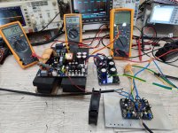
After long wait, I had time to listen to the amplifier today.
I have to admit that this amplifier sounds just amazing.
Great work Shann.
The test was conducted at +-53V with 13000uf extra capacitance on each rail.
The new SMPS 630 is used above
I might be able to build it into a box on later stage.
I have to admit that this amplifier sounds just amazing.
Great work Shann.
The test was conducted at +-53V with 13000uf extra capacitance on each rail.
The new SMPS 630 is used above
I might be able to build it into a box on later stage.
Attachments
Last edited:
After long wait, I had time to listen to the amplifier today.
I have to admit that this amplifier sounds just amazing.
Great work Shann.
The test was conducted at +-53V with 13000uf extra capacitance on each rail.
I might be able to build it into a box on later stage.
Nice!!!
After long wait, I had time to listen to the amplifier today.
I have to admit that this amplifier sounds just amazing.
Great work Shann.
The test was conducted at +-53V with 13000uf extra capacitance on each rail.
The new SMPS 630 is used above
I might be able to build it into a box on later stage.
Hi Sami
Are you sure your extra caps bank is really needed? What speakers are you driving? For home use?
Don't your 600VA units have enough current on transient?
Do you intend to have 1 or 2 power units for your stereo amplifier?
Mine is not yet finished in its enclosure, I'm still wondering .....
JM
- Home
- Group Buys
- PeeCeeBee V4H GB