Hi Sami
Are you sure your extra caps bank is really needed? What speakers are you driving? For home use?
Don't your 600VA units have enough current on transient?
Do you intend to have 1 or 2 power units for your stereo amplifier?
Mine is not yet finished in its enclosure, I'm still wondering .....
JM
That is not the SMPS600 in the picture 😉
Hi Sami
Are you sure your extra caps bank is really needed? What speakers are you driving? For home use?
Don't your 600VA units have enough current on transient?
Do you intend to have 1 or 2 power units for your stereo amplifier?
Mine is not yet finished in its enclosure, I'm still wondering .....
JM
Dear Jean,
The extra capacitance board is not needed, the SMPS can provide the needed transients without the extra capacitance.
I am planning to use 2 SMPS units, one for each channel.
The extra capacitance board shown as the new SMPS-630 can tolerate extra capacitance up to 14000uF per rail, maybe more. this is because some people just like to add extra capacitance. and that was something to implement in the new design.
However, the SMPS-600 CANNOT handle that extra capacitance.
Thanks
Ok, thanks ..... Very clear.
Mine already has a huge headroom, no need for extra caps.
JM
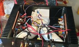
After long wait, I had time to listen to the amplifier today.
I have to admit that this amplifier sounds just amazing.
Great work Shann.
The test was conducted at +-53V with 13000uf extra capacitance on each rail.
The new SMPS 630 is used above
I might be able to build it into a box on later stage.
That is V4 on pic?
That is V4 on pic?
I really have to check it out, but it is old one
Problem with hum
Hi Shaan,
There is hum due to gnd loop when I have the amp directly connected to my CD (Esoteric K-03 SACD).
Same hum when I have only one channel connected. No problem with IPad or IPhone.
I use one transformer 2x36 V 500 VA and two 47.000 caps, common for both channels
And I have 2mm ceramic isolators for output mosfets.
Both heatsinks are connected to power supply's 0V ground.
Noticed that hum is less when I have gnd-loop breakers there.
Can I avoid these connections (The cables from 0 volt to heatsinks) ?
Attachments
Last edited:
Hi Shaan,
can I use the MJE340G/MJE350 that I already have in hand instead of KSE340/KSE350 VAS transistors ?
can I use the MJE340G/MJE350 that I already have in hand instead of KSE340/KSE350 VAS transistors ?
Hi Shaan,
There is hum due to gnd loop when I have the amp directly connected to my CD (Esoteric K-03 SACD).
Same hum when I have only one channel connected. No problem with IPad or IPhone.
I use one transformer 2x36 V 500 VA and two 47.000 caps, common for both channels
And I have 2mm ceramic isolators for output mosfets.
Both heatsinks are connected to power supply's 0V ground.
Noticed that hum is less when I have gnd-loop breakers there.
Can I avoid these connections (The cables from 0 volt to heatsinks) ?
Hi Theodosis.
When using a metal chassis with heatsinks only one connection from 0V to chassis floor through ground loop breaker is recommended. After doing that you can remove the heatsink connections to 0V.
Hi Shaan,
can I use the MJE340G/MJE350 that I already have in hand instead of KSE340/KSE350 VAS transistors ?
Yes you can. But the G type probably has a higher hFE. See if you can get both same suffixed. Or use a hFE meter to sort out a couple pairs that has closer hFEs.
Post-Lockdown GB update: 🙂
Greg1017 - 2 PCBs + MOSFETS
Torvbakkane - 6 PCBS
satmmc86 - 2 MODULES
Greg1017 - 2 PCBs + MOSFETS
Torvbakkane - 6 PCBS
satmmc86 - 2 MODULES
Hi Theodosis.
When using a metal chassis with heatsinks only one connection from 0V to chassis floor through ground loop breaker is recommended. After doing that you can remove the heatsink connections to 0V.
Sorry but I'm not sure that I understand this 😕 Could you please draw a scheme? I plan to use a ground loop breaker
Sorry but I'm not sure that I understand this 😕 Could you please draw a scheme? I plan to use a ground loop breaker
See, the heatsinks are electeically connected to the chassis, right? So you don't need to connect each heatsink to power supply ground individually. Just one connection from chassis base plate to power supply ground will be enough. In that connection use the ground loop breaker.
See, the heatsinks are electeically connected to the chassis, right? So you don't need to connect each heatsink to power supply ground individually. Just one connection from chassis base plate to power supply ground will be enough. In that connection use the ground loop breaker.
Thanks, now I am sure I have understood 🙂
Preamplifier update:
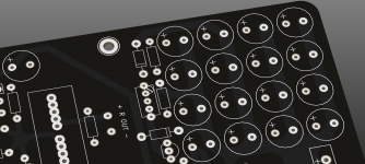
Got an email from PCB fab that they're back into full production. So placed order for a couple prototypes for the upcoming peeceebee preamp. In a couple weeks will get them at hand. The board is quite large with the onboard power supply, about 170mm by 120mm. I didn't make it super compact like the amps so assembling will be easier (a few electrolytics will need to be soldered though (check attachment) 🙂). There will be some manual settings alike the amps, including fine trimming of the power rails.
Got an email from PCB fab that they're back into full production. So placed order for a couple prototypes for the upcoming peeceebee preamp. In a couple weeks will get them at hand. The board is quite large with the onboard power supply, about 170mm by 120mm. I didn't make it super compact like the amps so assembling will be easier (a few electrolytics will need to be soldered though (check attachment) 🙂). There will be some manual settings alike the amps, including fine trimming of the power rails.
Attachments
Hi Theodosis.
When using a metal chassis with heatsinks only one connection from 0V to chassis floor through ground loop breaker is recommended. After doing that you can remove the heatsink connections to 0V.
Hi Shaan,
Done as suggested but there is no improvement with the hum.
Probably the ground loop is with the CD. The signal ground is connected to chassis in the CD.
So can I have the amp power supply 0Volt not connected to chassis ?
Hi Shaan,
Done as suggested but there is no improvement with the hum.
Probably the ground loop is with the CD. The signal ground is connected to chassis in the CD.
So can I have the amp power supply 0Volt not connected to chassis ?
Not connecting the amp power supply 0V to chassis may result into oscillation, so keep it connected.
You can try this and see if it improves:
Take a 10ohm 1/4watt resistor and a 100nF ceramic capacitor. Solder them in parallel. Intall this network in series with the SGND connection by cutting the SGND wire and soldering it in the middle. Do for both channel.
GB V4H
Faizal- One pair of tested modulePost-Lockdown GB update: 🙂
Greg1017 - 2 PCBs + MOSFETS
Torvbakkane - 6 PCBS
satmmc86 - 2 MODULES
- Home
- Group Buys
- PeeCeeBee V4H GB