I'll have to see the curves but I will be surprised if its a large improvement. You might get more benefit from caps across the most distant drivers to increase the amount of shading with frequency, with a relatively high corner frequency so only the treble where the worst combing occurs is affected. Too much of that will shrink the vertical window but it or the DSP equivalent does help with the combing in the top octave.
I spent a lot of time simulating today also trying to improve response at the standing ear height but without much progress, even when doing the equalization with the mic 250mm above array center. Regardless of mic height, I always ended up with a bass hump of about 5 db. For some reason I can't explain, in my shelf shaded array and no other frequency shading, the bass level increases with mic height.
Interesting but not surprising when you think about it - yesterday's phase correction only holds at the equalization height .
Believe me, it is an improvement. I know you're looking at shading drivers before the 90 degree phase angle, but with the bigger drivers, like the TC9, some interference can certainly be tolerated to fill in. See it as a sort of anti-aliasing.
I've already sen the graphs, I just want more time to work out the best numbers. I'm always running out of time lately.")
I've already sen the graphs, I just want more time to work out the best numbers. I'm always running out of time lately.
I've had to compromise that 90 degree thing. Shading before 90 degrees leads exclusive of other considerations narrows the vertical window. It remains key to a seated only filter set, though, and a rough guideline otherwise - if the delta path length at some frequency exceeds 90 degrees then providing some attenuation there for the driver may help
It is a bit of a balancing act. The original idea of a floor to ceiling array, acting somewhat like an infinite array isn't that flawed, so improving upon that particular idea isn't simple or straight forward. But it may end up doable and get us a performance boost.
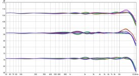
Here's the new schematic compared to my earlier shelf shaded example and an unshaded array:
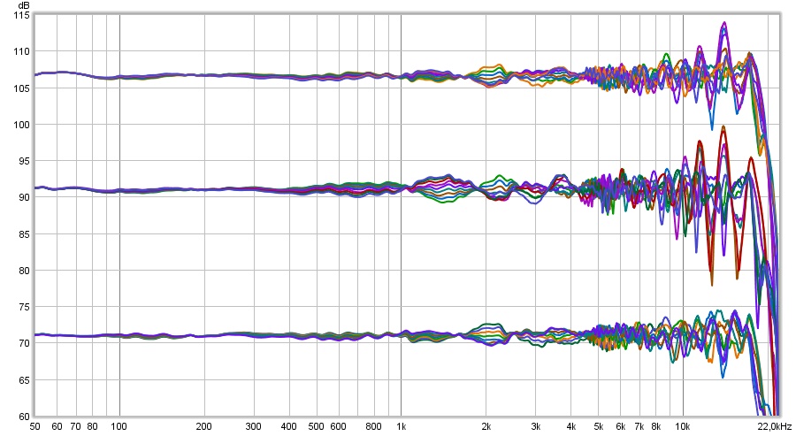
Top one is the earlier shelf shaded example (shown before on this thread), middle one is the unshaded array and the bottom one is my new suggestion, the one with extra inductors to shade the top end.
It is easy to see, as these are raw in-room results, the differences. Based on this graph alone, I'd pick the bottom graph as a clear winner. It has less variation, similar processing on all graphs, including floor and ceiling reflections.
But let's examine it a bit closer. If I show the same graphs with psycho-acoustic shading we get a slightly different picture:
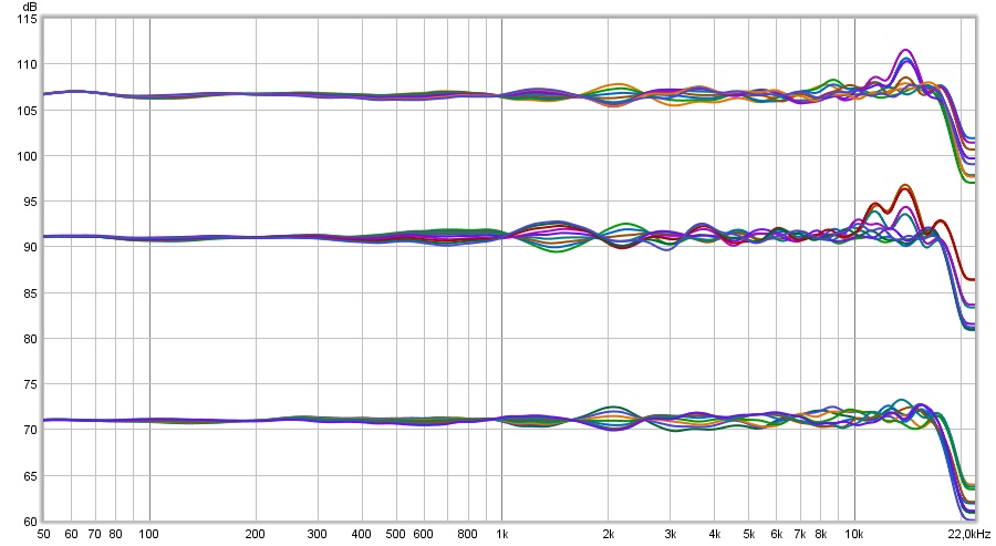
Even though the unshaded array has the biggest wiggles, we might state that it does keep a good balance at each position. Something I'd agree on as that is how I perceive my array. It shows great bundling of these results. While there are lots of wiggles, they are averaging out on a similar balance.
Now we see that the shaded examples improve on the top end, especially my new found shading logic. However the balance does show more variation.
Another look, this time with 1/3 octave smoothing:
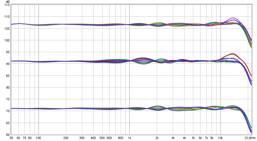
Because I'm not in the middle of the array, you see that the bundling is less ideal than that of an unshaded array. This is why I said I need more time/work to finish this up. I'd like to get close to the bundling of an unshaded array, while keeping the upper advantage. I do think it should be possible. As stated before, I'm not looking for a complete wiggle free solution, as it will be very hard to keep that while adding natural floor and ceiling reflections. Plus I don't think that is the secret to success.
Part of what makes the array principle work for me is how I can get away with less treatment and still have/get awesome results. The multiple drivers create that, nothing else. It averages out a lot of strong reflections you'd notice with single driver solutions. Unless you'd have room for big waveguide or horn type speakers. I still get a high direct sound compared to reflected sound balance and can negate the influence of floor and ceiling reflections without treatment, giving me a clear look into every song as if you're there.
What I robbed from the room in the form of damping/absorbing first reflections I make up for with the ambient channels. Making it possible to get a neutral tonal balance over a wide area and great imaging. These were the main points for me to go with arrays.
So I'll be on the sim wagon to see if I can have my cake and eat it too!
I'm getting closer and believe it should be possible to find a combination that works, out there in a room.
If you go for a wiggle free performance let me warn you: don't ever look at what happens at ear positions, you'll go nuts! Go build big barriers to try and stop that from happening or all that wiggle free performance has no meaning. I'll gladly consider adding wiggles of my own (and have done so) to improve the Stereo illusion.
Here's the new schematic compared to my earlier shelf shaded example and an unshaded array:
Top one is the earlier shelf shaded example (shown before on this thread), middle one is the unshaded array and the bottom one is my new suggestion, the one with extra inductors to shade the top end.
It is easy to see, as these are raw in-room results, the differences. Based on this graph alone, I'd pick the bottom graph as a clear winner. It has less variation, similar processing on all graphs, including floor and ceiling reflections.
But let's examine it a bit closer. If I show the same graphs with psycho-acoustic shading we get a slightly different picture:
Even though the unshaded array has the biggest wiggles, we might state that it does keep a good balance at each position. Something I'd agree on as that is how I perceive my array. It shows great bundling of these results. While there are lots of wiggles, they are averaging out on a similar balance.
Now we see that the shaded examples improve on the top end, especially my new found shading logic. However the balance does show more variation.
Another look, this time with 1/3 octave smoothing:
Because I'm not in the middle of the array, you see that the bundling is less ideal than that of an unshaded array. This is why I said I need more time/work to finish this up. I'd like to get close to the bundling of an unshaded array, while keeping the upper advantage. I do think it should be possible. As stated before, I'm not looking for a complete wiggle free solution, as it will be very hard to keep that while adding natural floor and ceiling reflections. Plus I don't think that is the secret to success.
Part of what makes the array principle work for me is how I can get away with less treatment and still have/get awesome results. The multiple drivers create that, nothing else. It averages out a lot of strong reflections you'd notice with single driver solutions. Unless you'd have room for big waveguide or horn type speakers. I still get a high direct sound compared to reflected sound balance and can negate the influence of floor and ceiling reflections without treatment, giving me a clear look into every song as if you're there.
What I robbed from the room in the form of damping/absorbing first reflections I make up for with the ambient channels. Making it possible to get a neutral tonal balance over a wide area and great imaging. These were the main points for me to go with arrays.
So I'll be on the sim wagon to see if I can have my cake and eat it too!
I'm getting closer and believe it should be possible to find a combination that works, out there in a room.
If you go for a wiggle free performance let me warn you: don't ever look at what happens at ear positions, you'll go nuts! Go build big barriers to try and stop that from happening or all that wiggle free performance has no meaning. I'll gladly consider adding wiggles of my own (and have done so) to improve the Stereo illusion.
Attachments

like my friend Ronald, I too am zeroing in on a solution. I had a great deal of frustration trying to stretch the vertical listening window farther than it wanted to go. Then I gave up and decided to settle for an optimized seated height. With that, the standing height variation is no worse than any variation (except unshaded) I tried until >10 khz.
Here is what the unshaded array does:
I'm using a two step equalization process. First I equalize to the listening window average independent of floor and ceiling reflections, then to the room responses averaged over the vertical window to get the top group of traces in the graph.
After a lot of tearing out what is left of my hair, I now have this from a mix of both shelf and frequency shading:
The top group of traces is the seated position and 2" and 4" above and below it. The lower two traces are at 400 and 500 mm. Standing is obviously too a relaxed standard but its still within +/-3 db at 400mm.
My current shading is best explained by filter graphs absent equalization:
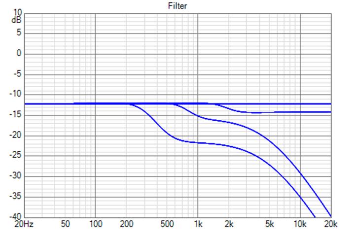
I started with the Dave Smith shading coefficients, implemented shelves to preserve headroom on the low end, increased the top shelf attenuation from .9 to 2 db. then added low pass filters for the outer drivers to cut them off as soon as I could without increasing the response variation in the regions above cutoff.
Here is what the unshaded array does:
I'm using a two step equalization process. First I equalize to the listening window average independent of floor and ceiling reflections, then to the room responses averaged over the vertical window to get the top group of traces in the graph.
After a lot of tearing out what is left of my hair, I now have this from a mix of both shelf and frequency shading:
The top group of traces is the seated position and 2" and 4" above and below it. The lower two traces are at 400 and 500 mm. Standing is obviously too a relaxed standard but its still within +/-3 db at 400mm.
My current shading is best explained by filter graphs absent equalization:
I started with the Dave Smith shading coefficients, implemented shelves to preserve headroom on the low end, increased the top shelf attenuation from .9 to 2 db. then added low pass filters for the outer drivers to cut them off as soon as I could without increasing the response variation in the regions above cutoff.
Attachments

I think I managed to win some terrain too ...
Top graph is the first shelf shaded attempt as seen before,
Center is unshaded
Bottom is the new shelf shading with top end compensation.
Still passive filters only, shelf shaded plus inductor top end compensation. I sort of cheated, but it's very doable in wiring. I made the center group of 5 drivers unshaded and centered around my desired 1 meter listening height. The group right around that is 3 drivers below that center group and two drivers above it, so I could more easily shade their (very) top end.
The rest is back to normal as groups of 5 drivers, but I needed that tweak to get more bundling of the drivers around the center axis. I think I did quite OK. Maybe there's more to be had, as always.
Heights span +100 to -100 around the listening axis of 1 meter, in 25 mm steps.
The results without smoothing:

I'd say a clear difference. I think even the raw results look pretty awesome with the exact same settings used to make all three graphs.
Normalised comparison between unshaded and shaded 6.0...
As the boost on the upper end for the group of 5 drivers is no higher than it was for the unshaded array, I'd say that this should be save to implement without worrying.
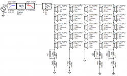
The shading schematic I used:

(look at the height numbers to see how I grouped the drivers)
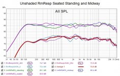
To make this set complete, I've included the 1.70 meter standing height of both the unshaded and shaded array:
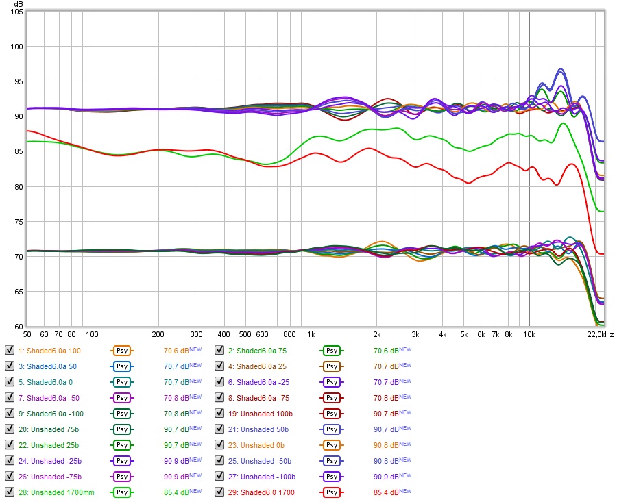
The unshaded array (green) is a little bright standing up. I guess I'd have to trade that in for a little darker (red) if I go ahead with shading...
I'm pretty sure I could live with that...
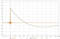
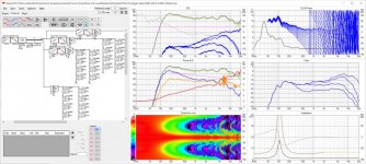
As long as I'm feeling a little victorious about this improvement, here's the predicted IR & Step (from Vituixcad)*
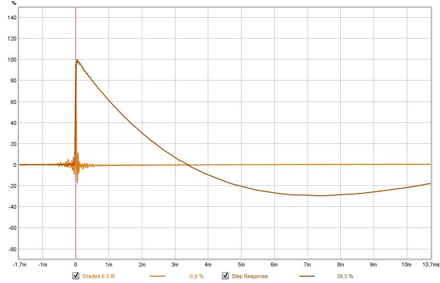
*= first time I spelled it right I think
...Top graph is the first shelf shaded attempt as seen before,
Center is unshaded
Bottom is the new shelf shading with top end compensation.
Still passive filters only, shelf shaded plus inductor top end compensation. I sort of cheated, but it's very doable in wiring. I made the center group of 5 drivers unshaded and centered around my desired 1 meter listening height. The group right around that is 3 drivers below that center group and two drivers above it, so I could more easily shade their (very) top end.
The rest is back to normal as groups of 5 drivers, but I needed that tweak to get more bundling of the drivers around the center axis. I think I did quite OK. Maybe there's more to be had, as always.
Heights span +100 to -100 around the listening axis of 1 meter, in 25 mm steps.
The results without smoothing:
I'd say a clear difference
. I think even the raw results look pretty awesome with the exact same settings used to make all three graphs.Normalised comparison between unshaded and shaded 6.0...
As the boost on the upper end for the group of 5 drivers is no higher than it was for the unshaded array, I'd say that this should be save to implement without worrying.
The shading schematic I used:
(look at the height numbers to see how I grouped the drivers)
To make this set complete, I've included the 1.70 meter standing height of both the unshaded and shaded array:
The unshaded array (green) is a little bright standing up. I guess I'd have to trade that in for a little darker (red) if I go ahead with shading...
I'm pretty sure I could live with that...
As long as I'm feeling a little victorious about this improvement, here's the predicted IR & Step (from Vituixcad)*
*= first time I spelled it right I think
Attachments
Last edited:
Yes, you did!
I need to learn that trick of toggling between two images.
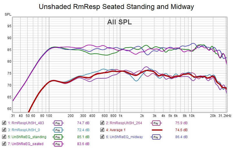
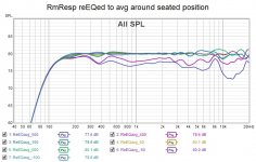
I finally realized that my best chance of getting good responses both seated and standing was to mount the array on the wall with the center of the array midway between the seated and standing ear heights. This is feasible with my construction using french cleats.
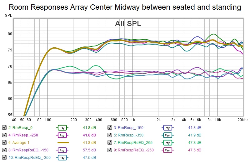
As before I first equalized to 15V listening window average and the re-EQed the room response to the average around the seated position. This left the standing ear height still an outlier but not so far out. The ear height group is good but not quite as good as with center of array very close to ear height.
I need to learn that trick of toggling between two images.
I finally realized that my best chance of getting good responses both seated and standing was to mount the array on the wall with the center of the array midway between the seated and standing ear heights. This is feasible with my construction using french cleats.
As before I first equalized to 15V listening window average and the re-EQed the room response to the average around the seated position. This left the standing ear height still an outlier but not so far out. The ear height group is good but not quite as good as with center of array very close to ear height.
Attachments
I need to learn that trick of toggling between two images.
It's just an animated gif, with the two images shown for a couple of seconds and repeat indefinitely. Made with Animation shop, part of the old Paint Shop Pro (outdated but still useful).
It's mimicking how I work with Vituixcad, with two separate instances open and switching between them on the taskbar. Makes it easy to see if a tweak is going in the right direction.
I managed to tighten up the standing response at ~5 KHz without any other obvious drawbacks. Should run the whole sequence again to be sure though.
Little tweaks go a long way.
Incidentally, using an expanded arrangement means you can sit closer to the array without seeing much combing, something you could not do with a full array of TC9s. In my measurements, the minimum distance was above 1.5x the array length when using TC9s full out. This might be important because by sitting closer you will be more in the direct field and have reflections arrive later. This will definitely be a plus for clarity and imaging.
That is indeed true. I've been using 3m listening distance in my sims which is about 1.5x the height.
The last time I looked at expanding concept, I took it too far and ended up with a single tweeter at the center flanked by two midranges that also needed to be robust - not really an array anymore.
But the EQ I'm using in simulation of my 32xSB65 array effectively expands from a central section of 8 unshaded drivers using both frequency and shelf shading:

For the graphs shown, the array was EQed for flat room response at 3m then the listening distance was reduced to 2m. There is some combing in the 6-10 Khz range due to relatively long delayed floor and ceiling reflections (just like at 3m) but the shading takes care of combing from the direct wave. You would want to reEQ if 2m was your primary listening distance but the sim shows combing wouldn't be a problem there.
And this is a seated optimization. If I wanted a taller vertical listening window, I would not have the 12 khz LPF on the driver group flanking the central 8 drivers.
The last time I looked at expanding concept, I took it too far and ended up with a single tweeter at the center flanked by two midranges that also needed to be robust - not really an array anymore.
But the EQ I'm using in simulation of my 32xSB65 array effectively expands from a central section of 8 unshaded drivers using both frequency and shelf shading:
For the graphs shown, the array was EQed for flat room response at 3m then the listening distance was reduced to 2m. There is some combing in the 6-10 Khz range due to relatively long delayed floor and ceiling reflections (just like at 3m) but the shading takes care of combing from the direct wave. You would want to reEQ if 2m was your primary listening distance but the sim shows combing wouldn't be a problem there.
And this is a seated optimization. If I wanted a taller vertical listening window, I would not have the 12 khz LPF on the driver group flanking the central 8 drivers.
Attachments
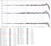
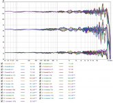
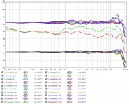
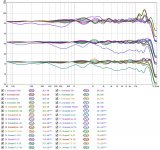
I was looking for an upgrade of standing performance, hoping I'd get it without any big compromises. I think I've managed to achieve it:
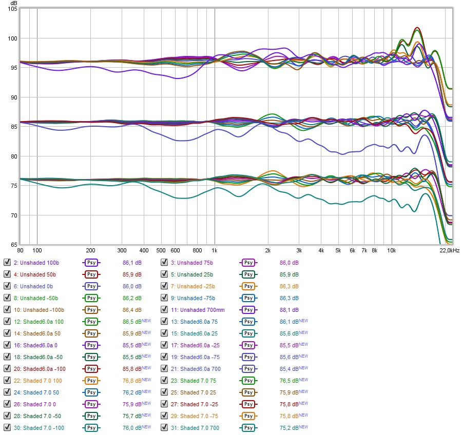
Top - Unshaded (as seen before)
Middle - Shaded 6.0 (seen previously shelf shade + top end compensation)
Bottom - Shaded 7.0 (new with the task of better standing, 1.7 meter, performance)
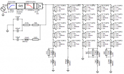
I've tried many things, in the end it was quite simple. I just had to learn about passive compensation filters like notches etc. Here's the schematic:

All it took was an extra cap and a slight change in component values. I may yet find ways towards further improvements. But most of it is within plus/minus 1 dB from 900 cm to 1100 cm.
The difference in the 5 KHz dip is almost 1.5 dB in favor of this last schematic. Not bad for a passively filtered frequency dependent solution I'd say.
I'll repost this on my own thread as well.
Top - Unshaded (as seen before)
Middle - Shaded 6.0 (seen previously shelf shade + top end compensation)
Bottom - Shaded 7.0 (new with the task of better standing, 1.7 meter, performance)
I've tried many things, in the end it was quite simple. I just had to learn about passive compensation filters like notches etc. Here's the schematic:
All it took was an extra cap and a slight change in component values. I may yet find ways towards further improvements. But most of it is within plus/minus 1 dB from 900 cm to 1100 cm.
The difference in the 5 KHz dip is almost 1.5 dB in favor of this last schematic. Not bad for a passively filtered frequency dependent solution I'd say.
I'll repost this on my own thread as well.
Attachments
Last edited:
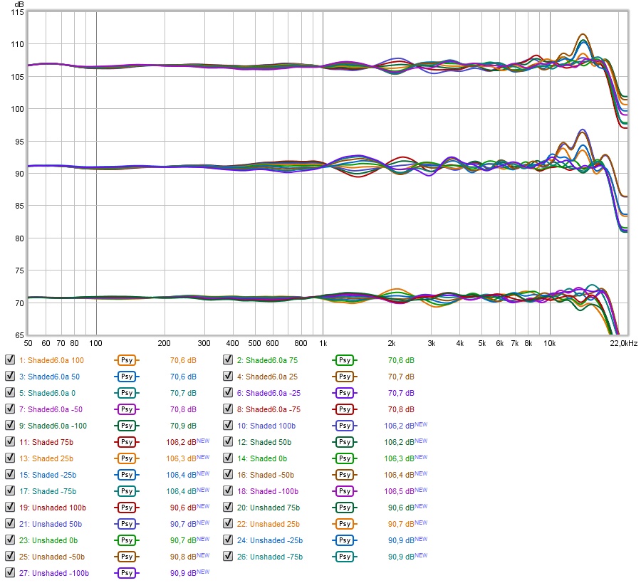
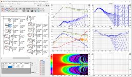
I took another look at the fine frequency shaded array today.
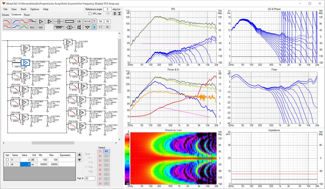
I started out with a DSP/amp channel for the center driver and each successive flanking pair. I got a great response but then effectively combined the two groups flanking center. The response remained great:

The filter cutoff frequencies were chosen to cut each driver pair off before their delta path length phase shift exceeded 90 degrees. This eliminates all subtractive combining and thus makes for a ripple free frequency response in free space. There is not even a hint of combing. Unfortunately, when floor and ceiling reflections are included we do get combing above 6 khz because of the longer delta path lengths for these reflections but as shown earlier a thin layer of absorption on floor (carpet) and ceiling will reduce/eliminate them.
But how tall is the vertical window? Well, there are 5 drivers each getting full range response although the outermost pair of the 5 are down 2 db to reduce the rising response I found in the treble as the mic was raised off axis. 5 times 3.5" is 17.5" so it will be something less than that.
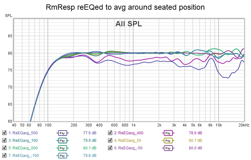
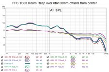
Here is the room response before EQ and after EQ to the avg over 0 to 100 mm offsets.

Yes its +/- 1db below 10 khz and within +/-2db above 10 khz over an 8" vertical window!!! Its hard to imagine doing better for a seated only listening window. Too bad actually implementing this would be somewhat extravagant.
I started out with a DSP/amp channel for the center driver and each successive flanking pair. I got a great response but then effectively combined the two groups flanking center. The response remained great:
The filter cutoff frequencies were chosen to cut each driver pair off before their delta path length phase shift exceeded 90 degrees. This eliminates all subtractive combining and thus makes for a ripple free frequency response in free space. There is not even a hint of combing. Unfortunately, when floor and ceiling reflections are included we do get combing above 6 khz because of the longer delta path lengths for these reflections but as shown earlier a thin layer of absorption on floor (carpet) and ceiling will reduce/eliminate them.
But how tall is the vertical window? Well, there are 5 drivers each getting full range response although the outermost pair of the 5 are down 2 db to reduce the rising response I found in the treble as the mic was raised off axis. 5 times 3.5" is 17.5" so it will be something less than that.
Here is the room response before EQ and after EQ to the avg over 0 to 100 mm offsets.
Yes its +/- 1db below 10 khz and within +/-2db above 10 khz over an 8" vertical window!!! Its hard to imagine doing better for a seated only listening window. Too bad actually implementing this would be somewhat extravagant.
Attachments
Last edited:
well a Motu 24AO has 24 channels of 32 bit DAC for (only) $995
If this were the bad old days when I was young and foolish and had prototyping infrastructure and lab at hand, I would whip up a small LM3886 board with a couple of op amps and have 24 of them built. How hard can it be ? (famous last words)
Chances the number of channels can be cut down without giving much up.
got it down to 9 amps by combining adjacent pairs at the low end. I almost didn't need to re-EQ. Could probably combine one or two more pairs without damage.
3 amps will go down to 1 amp at the high end with just little trouble
so 8 amps for sure; possibly as few as 6
Soon I will need to try the same thing for the 32x SB65 array...
3 amps will go down to 1 amp at the high end with just little trouble
so 8 amps for sure; possibly as few as 6
Soon I will need to try the same thing for the 32x SB65 array...
I took another look at the fine frequency shaded array today.

Yes its +/- 1db below 10 khz and within +/-2db above 10 khz over an 8" vertical window!!! Its hard to imagine doing better for a seated only listening window. Too bad actually implementing this would be somewhat extravagant.
Can you please try with IIR? Then it can be implemented with active analogue.
The result with a straightforward replacement of LinPhase filter blocks with corresponding IIR filter blocks isn't pretty, even with delay in unfiltered channel that tries to match the IIR filter delay. I knew the delay was problematic but I didn't realize just how problematic it would be. The vertical directivity widened up in the midrange and we are left with floor ceiling bounce nulls. Passive will require a different approach, one I haven't thought of yet.

Attachments
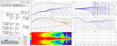
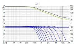
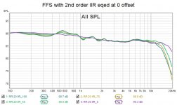
and I can get a fairly good response with 2nd order IIR. any higher order and the phase rotation kills it.
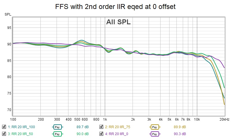
It suffers a little in the mid bass and there is a loss of treble going off the vertical axis. This is without much tweaking so its encouraging.
It suffers a little in the mid bass and there is a loss of treble going off the vertical axis. This is without much tweaking so its encouraging.
Attachments
- Home
- Loudspeakers
- Full Range
- Full range line array for wall or corner placement