Welcome to the sims ra7! I hope you'll soon have as much fun with it as we do. Very educational! I hope you did start with the head start nc535 gave us, with a lot of data readily available for the TC9? Link here: https://www.diyaudio.com/forums/full-range/337956-range-line-array-wall-corner-placement-55.html#post6205129
wow... I did miss that... wish I had known sooner. But no worries... I am still fumbling around so this will be a huge help. Thank you!
Question to you and NC: what is filter function file doing? Is it adding a floor reflection, a ceiling reflection, or both? Should I remove the ceiling and floor reflection from the room section when using the filter file?
If by filter function you mean the one loaded into the G(f) block, it performs equalization. My current method of creating those files is by exporting in-room response(driver offsets) over the target range of listening heights. (Note that a negative vertical driver offset is equivalent to moving the mic up.) I average those exported responses in REW with the averaging obviating the need for smoothing, then bring the average into Vituix calculator tool for mirroring, which is equivalent to impulse response inversion. While exporting the room responses you would ordinarily have boxes for floor and ceiling responses checked. Prior to that, enter the floor and ceiling distances from the center of the array....
My way of doing things is slightly different. I have made a global pré-EQ with REW to get things in the ball park (relative flat response).
Next I export the "Listen win SPL" from Vituix and run that one through DRC-FIR (I use REW to normalise it first).
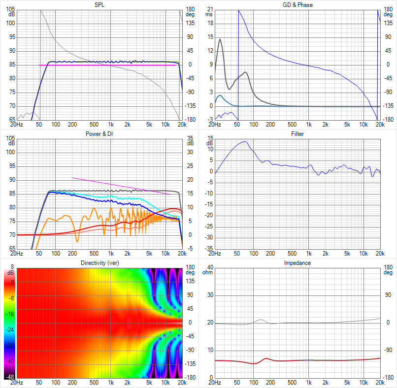
After creating the FIR correction with DRC I convolve the outcome with the pré-EQ. Adjust SPL in REW and export it as a filter for Vituix. That's what's shown in the Vituix graphs I presented. A neat flat listening window will be the result.

Next I change the Room settings and export the "In room response" for each height of interest. Indeed a negative number on driver offset is representing a higher microphone position. See the graphs that show Floor, Ceiling and speaker position.
For each height you've got to adjust the floor and ceiling heights too. It's a bit of work but you get used to it.
After importing all of the in room heights within REW I make an average and
use the inverse of that to make a second correction which is convolved with all height graphs. That's the one I show in the REW graphs.
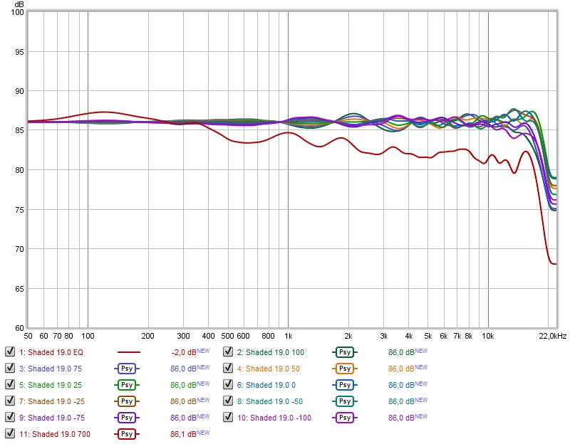
I use 100, 75, 50, 25, 0, -25, -50, -75 and -100 as actual differences from my 1 meter listening height. Meaning 100 is 100 above 1 meter is 1100 mm or 1,1 meter. To get to 1.1 meter I had to offset the drivers with -100 (the Y value) in VituixCad. And also adjust the floor and ceiling height to represent that total height change.
My results are with floor and ceiling reflections set to on, but absorption set to 12 dB (only looking for general trends). I see that the latest Vituix has different absorption levels for all wall, floor and ceiling reflections.
I have made mine when there was still one number for all planes. This will bring even more usable data as one can set the absorption per plane.
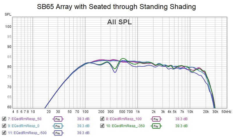
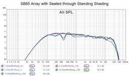
Here's a comparison between unshaded and (frequency) shaded with both floor and ceiling reflections set to "on" at -6 dB level:
Next I export the "Listen win SPL" from Vituix and run that one through DRC-FIR (I use REW to normalise it first).
After creating the FIR correction with DRC I convolve the outcome with the pré-EQ. Adjust SPL in REW and export it as a filter for Vituix. That's what's shown in the Vituix graphs I presented. A neat flat listening window will be the result.
Next I change the Room settings and export the "In room response" for each height of interest. Indeed a negative number on driver offset is representing a higher microphone position. See the graphs that show Floor, Ceiling and speaker position.
For each height you've got to adjust the floor and ceiling heights too. It's a bit of work but you get used to it.
After importing all of the in room heights within REW I make an average and
use the inverse of that to make a second correction which is convolved with all height graphs. That's the one I show in the REW graphs.
I use 100, 75, 50, 25, 0, -25, -50, -75 and -100 as actual differences from my 1 meter listening height. Meaning 100 is 100 above 1 meter is 1100 mm or 1,1 meter. To get to 1.1 meter I had to offset the drivers with -100 (the Y value) in VituixCad. And also adjust the floor and ceiling height to represent that total height change.
My results are with floor and ceiling reflections set to on, but absorption set to 12 dB (only looking for general trends). I see that the latest Vituix has different absorption levels for all wall, floor and ceiling reflections.
I have made mine when there was still one number for all planes. This will bring even more usable data as one can set the absorption per plane.
Here's a comparison between unshaded and (frequency) shaded with both floor and ceiling reflections set to "on" at -6 dB level:
Attachments
Last edited:
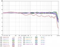
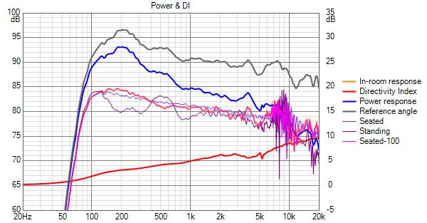
Here's a comparison of a single TC9 and the array, with both 6 dB damped floor and ceiling reflections:
Beside the SPL difference it might explain why we like the arrays as much as we do...
At least I know I do 😉. Clearly the array has advantages in a room. Making use of the multiple drivers it will also be
less susceptible for objects within a room. As noted many times: be aware of parallel planes and ridges!
Can you believe the single TC9 actually needed higher EQ levels to achieve this?
Attachments


Last edited:
Awesome results, Ronald! I can't approach them standing but my seated optimization has less variation, as one might expect. I'm still searching for a good seated and standing scheme.
I just realized that the large rise towards the bass that I see in my standing sims is due almost entirely to the wall, floor and ceiling reflections. Its not boundary interference but more bass boost seeming to be a function of height. More likely, its loss of higher frequencies due to shading. If I sim and equalize without these enabled, I get very acceptable standing results. With them enabled, response is highly dependent on position relative to the walls and the amount of absorption, which isn't modeled well by a fixed value. There is a lot to look at because of that.
I've just started using the Vituix "copy selected as overlay" feature accessed by right clicking in the room response graph. Do a sim e.g. at zero driver offset then place cursor over the orange trace as select copy selected as overlay. Do a sim at another offset and the prior results remain for comparison without bringing them into ReW. You can do multiple overlays and click the "traces" button to get a pop up where you can rename them and/or delete them.
This sim was done with just floor and ceiling reflections. Its standing result is much better than my fine frequency shaded seated optimized approach.
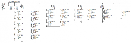
Here is a screen shot of the shading mechanism. I've bi-amped between 12 central drivers and 3 shelf shaded groups off a 2nd amplifier, otherwise a single amp would see ~2 ohm load. Two of the shelves have the drivers bypassed with caps to provide a low pass frequency shading effect.
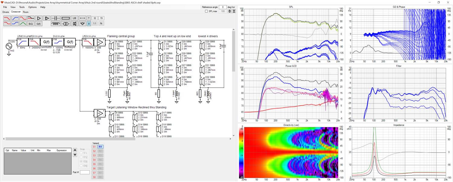
This approach shows some potential and if I can get it to work well enough, it minimizes the rewiring I would need to do. At first blush, the inductor values look too high to be practical (PE doesn't stock them) but I can do the shelves in DSP just as well without buying more electronics.
I just realized that the large rise towards the bass that I see in my standing sims is due almost entirely to the wall, floor and ceiling reflections. Its not boundary interference but more bass boost seeming to be a function of height. More likely, its loss of higher frequencies due to shading. If I sim and equalize without these enabled, I get very acceptable standing results. With them enabled, response is highly dependent on position relative to the walls and the amount of absorption, which isn't modeled well by a fixed value. There is a lot to look at because of that.
I've just started using the Vituix "copy selected as overlay" feature accessed by right clicking in the room response graph. Do a sim e.g. at zero driver offset then place cursor over the orange trace as select copy selected as overlay. Do a sim at another offset and the prior results remain for comparison without bringing them into ReW. You can do multiple overlays and click the "traces" button to get a pop up where you can rename them and/or delete them.
This sim was done with just floor and ceiling reflections. Its standing result is much better than my fine frequency shaded seated optimized approach.
Here is a screen shot of the shading mechanism. I've bi-amped between 12 central drivers and 3 shelf shaded groups off a 2nd amplifier, otherwise a single amp would see ~2 ohm load. Two of the shelves have the drivers bypassed with caps to provide a low pass frequency shading effect.
This approach shows some potential and if I can get it to work well enough, it minimizes the rewiring I would need to do. At first blush, the inductor values look too high to be practical (PE doesn't stock them) but I can do the shelves in DSP just as well without buying more electronics.
Attachments
Last edited:
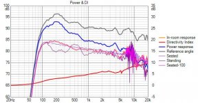
I did an active version of the previous passive shelf and frequency shaded array. I added 1" to the base thickness to raise the array and remeasured my and my wife's standing ear heights. This lowered the standing ear height offset by 50 mm and the difference is noticeable. But the improvement at standing heights is due more to adding shelf shading to the original frequency only shading than to this 10% reduction in standing offset.
I modeled the array tight in the corner with 12 db absorption on the near walls. The dips in the midbass at standing offset are a testament either to the inadequacy of those absorbers or the modelling but this standing response is miles better than what my seating optimization provided. The seated position looks just as good as the fine frequency shaded result but only after smoothing. Unsmoothed, it is rougher and I wonder if that matters.
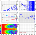
Here is the Vituix screenshot:
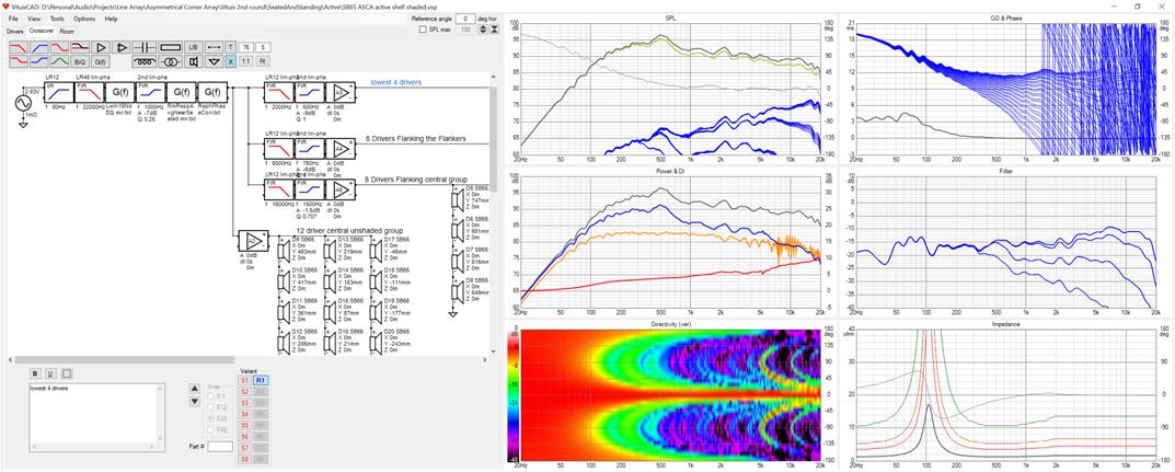
I modeled the array tight in the corner with 12 db absorption on the near walls. The dips in the midbass at standing offset are a testament either to the inadequacy of those absorbers or the modelling but this standing response is miles better than what my seating optimization provided. The seated position looks just as good as the fine frequency shaded result but only after smoothing. Unsmoothed, it is rougher and I wonder if that matters.
Here is the Vituix screenshot:
Attachments
I'm wondering if it would be viable to use frequency dependent shading on a CBT. Making the drivers work more together instead of letting only a few drivers work hard.
I bet that would make them sound more dynamic. Not that I have plans in that direction but I do wonder about the CBT projects that are out there with full range drivers.
To me it seems a shame to not be able to use the advantage of having many drivers share the load, on the other hand it is obvious what they were trying to achieve with the shading.
Just thinking out loud here. If you are running active, nc535, maybe it could help using some delay to help get rid of some patterns that originate from the fixed geometry of the drivers. Something like the ceiling splash is due to the fixed driver distances I presume. Maybe you could reduce those effects by adding some delay to mimic the bent CBT?
The recent couple of CBT threads got me thinking about this as well. I revived a CBT simulation I had from when I was choosing between straight and curved and took a look at it. The results were disappointing. I did achieve a marginal reduction in combing but one's hands are tied in working with the groundplane CBT. Amplitude shading opportunities are used to optimize directivity: implementing the CBT itself. That leaves frequency shading. One would think that cutting off the high frequencies for the drivers at the upper end of the curve would help because those drivers aim above the listener's ears and their directivity prevents the high end of their output from dispersing down to ear level. And it does help but the effect is small and is masked by the combing from the longer delayed ground reflection. Furthermore, if you implement frequency shading anywhere near the extent I've done on a straight array, your only full range drivers would be those close to the floor.
Another thing I noticed is that combing is worse on a CBT. Intuitively, this is because the array's curve away from the listener increases the delta path length. Not only is each driver raised above the previous one but it is also stepped back. Subtractive combining thus starts at a lower frequency. Ceiling splash due to loss of vertical directivity in the high end is also worse, again because of the higher delta path length but also because of the increasing tilt of the drivers towards the ceiling. Don Keele was well aware of these two things. He mentioned the loss of control at high frequency and always built 2-way arrays with large numbers of small tweeters so that it didn't occur into well into the treble.
One thing that I think may be worth trying, now that you mention it, is to electronically curve the array towards the listeners, instead of away from them as in a CBT. Carried to an extreme, this could/would focus the array on a single spot, the opposite of what i'm trying to do. I'm thinking just to delay the central unshaded group of drivers by enough to neutralize the delta path length to the furthest of the immediately adjacent flanking group. (unanticipated side effects aside 🙂)This might allow it to be unshaded as well without combining subtractively in the top octave. This should help because now my standing ear is at the upper edge of that unshaded group.

If you bend it the other way, the center (seated) array would be further away at standing position  ...
...
...Yes, but what matters is the delta path length - Center drivers to mic vs outer drivers to mic. If mic remains at center, this decreases. If mic is raised well above center then delta decreases for upper drivers and increases for lower drivers. Its not immediately clear which effect dominates but that is what I meant by unanticipated side effects. I'm betting on it still being a win because the lower drivers negative contribution will be attenuated by increase path length (minor effect) and driver directivity (increasing significance with frequency).
Initial results discouraging. Even a small delay of 60 usec tightened the beam instead of widening it.
Did you have any results yet, ra7? Are you simulating results with your tweeter solution?
I don't quite have results to share yet. Time is at a premium, but should have more time next week.
I am finding it instructive to model using ideal driver behavior rather than the measured response (provided kindly by nc35... thank you!). There are two schemes I am trying:
1. Sets of six drivers (I have 24 in total, not 25 like you two) plus one central tweeter. Currently simulating with just a TC9.
2. Expanding set with central tweeter, 12, 6, 4, 2, 1. This one shows promise. I am getting much smoother directivity change with this approach. See attached layout. Still very preliminary.
I definitely think a dedicated tweeter is the way to go having heard the improvement with the Fountek Neo CD 3.5H.
I was asking about directivity in your other thread, but there was something wrong with my simulation. I had added a driver but was not using it and it was totally screwing up the sim. So, removing it fixed the sim and now I do see reasonable results.
One question is about the floor and ceiling reflections. Turning them on does absolutely nothing to the results. What am I missing?
Attachments
On a slightly different note, I wanted to share some observations from my other speaker, JBL 2226 + JBL 2445 on the JBL 2380 horn. This produces absolutely stunning imaging when coupled with the Mid-side EQ and a 45 deg phase differential from 1 kHz - 8 kHz. The imaging is other worldly. There is so much emotional impact.
So, this got me thinking about what am I doing with the arrays. For sure, the arrays produce fewer reflections from the vertical plane. I was convinced that this would lead to better sound. But the JBL system does nothing to avert floor or ceiling reflections. It is true that the horn helps with early vertical reflections, but the woofer is omni up to 500 Hz. Moving the JBL system out into the room, 5 feet away from the side and back walls produces this really nice "wet" sound with a lot of late arriving energy that is really pleasing. This is what is missing the most with the arrays I feel. Wesayso too probably felt this and added the ambiance speakers.
So, I've been pondering about this for a while, but have no conclusions yet. I think my next build will be a compact monitor with a waveguide-loaded tweeter, something like the Heissman Acoustics designs. I want to plop them in the middle of the room and see what happens. The thinking is to reduce the source size as much as possible while keeping smooth directivity.
Haven't given up on the arrays yet though. Just have to find a large slot of time to work on them. Rewiring them is going to be a pain. I am thinking of using one of the Wavecor tweeters to make a smooth transition for the two TC9s.
P.S.: I had bought the BMS 4590 thinking it would be an improvement over the 2445s I've owned for a long time. But NO! The BMS drivers, while more refined do not produce the imaging or the emotional impact of the 2445s on the 2380 horn. So, the JBL engineers certainly knew what they were doing and there is something to be said about matching the horn to a particular driver. I checked and measured the crossover a dozen times, that wasn't it.
Last edited:
I had a huge reply all typed up, I looked at the horn/CD combo and provided the data sheets, but the jest of it is that I am glad to hear/read a noticeable improvement of the mid/side EQ with phase tricks... ...on something other than line arrays 🙂.
I would love to see the values used of both the EQ and phase tricks.
I liked the graphs of the horn, as it does stay quite constant at 0-15 degree
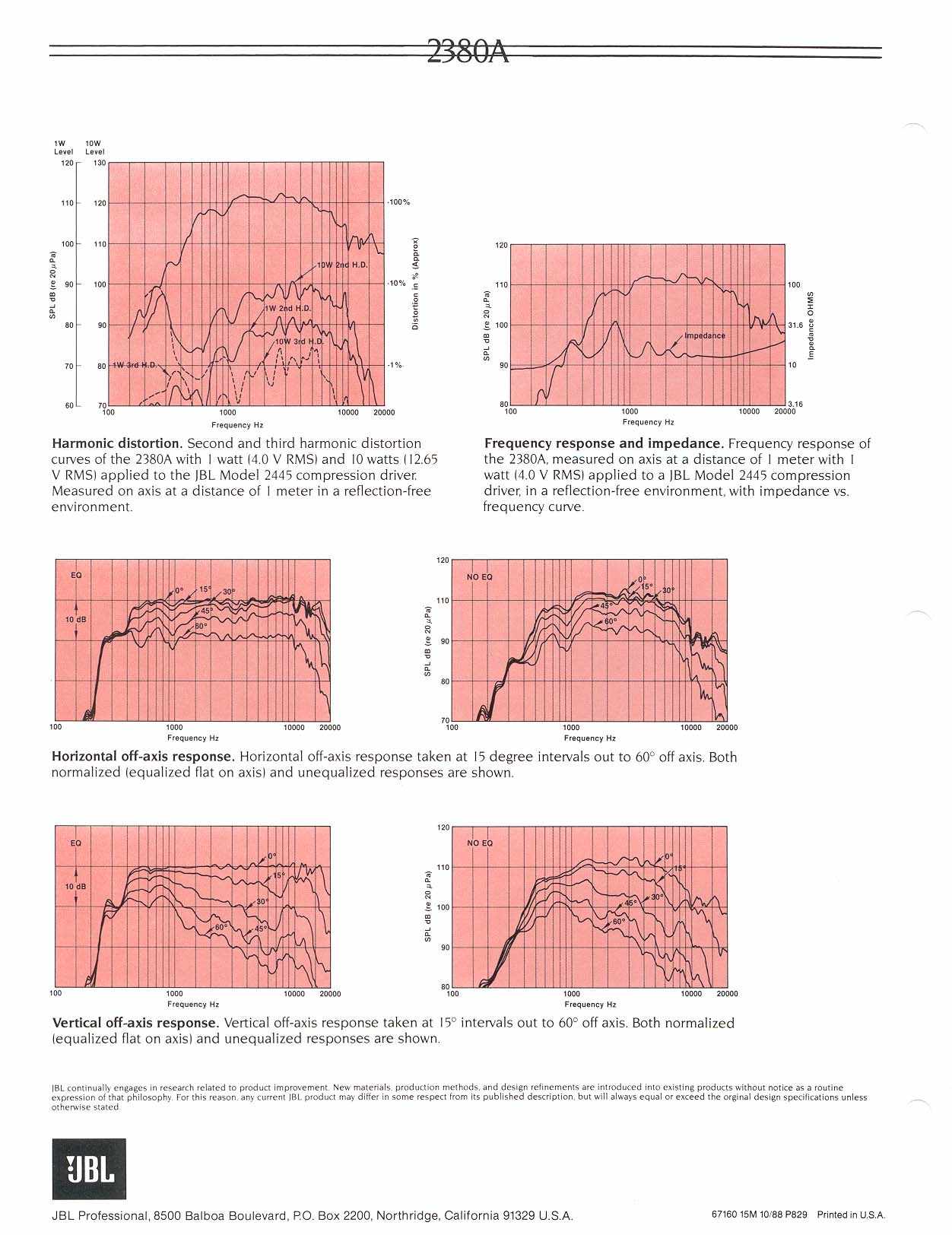
Source: Index of /images/jbl/specs/pro-comp/2380
Wouldn't you be worried going to a small compact speaker to lose a lot in dynamics?
If you managed the expanding array well enough to avoid the ceiling splash, indeed the floor/ceiling would not change much if anything at all. Something that was achieved with the fractal array as well.
The thing that worries me about those plans is the ruggedness of the tweeter. On Dunlavy's big WMTMW's the tweeter turned out to be the achilles' heel. Lots of reports of blown tweeters. So whatever you pick there must be capable enough. That's why I'm not ready to go all out in that direction and will stick to sharing the load on as many drivers as needed to make them have at least 15 dB head room over my desired output level.
(that JBL setup has way more than that (lol))
I simply don't have the room to go with a horn setup free standing, at least not while I'm in a happy relationship 😀. I've mentioned before, without any constraints big horns would be where I'd be at. Most probably with an array of low frequency drivers. Due to space (and relationship) concerns I'm milking out this array concept, and have no regrets so far. 🙂
Still adding to this post as I had written a lot more, like on the ambient setup. You're absolutely right on my reasons of including that, I'm trying to mimic a way better space that I have (and it works) as that "wet edge" makes it much more entertaining and holographic like. Together with mid side tweaks it becomes very entertaining! Without it, I could keep the imaging great, but with it, it has that true feel/thrill of being involved.
I would love to see the values used of both the EQ and phase tricks.
I liked the graphs of the horn, as it does stay quite constant at 0-15 degree
Source: Index of /images/jbl/specs/pro-comp/2380
Wouldn't you be worried going to a small compact speaker to lose a lot in dynamics?
If you managed the expanding array well enough to avoid the ceiling splash, indeed the floor/ceiling would not change much if anything at all. Something that was achieved with the fractal array as well.
The thing that worries me about those plans is the ruggedness of the tweeter. On Dunlavy's big WMTMW's the tweeter turned out to be the achilles' heel. Lots of reports of blown tweeters. So whatever you pick there must be capable enough. That's why I'm not ready to go all out in that direction and will stick to sharing the load on as many drivers as needed to make them have at least 15 dB head room over my desired output level.
(that JBL setup has way more than that (lol))
I simply don't have the room to go with a horn setup free standing, at least not while I'm in a happy relationship 😀. I've mentioned before, without any constraints big horns would be where I'd be at. Most probably with an array of low frequency drivers. Due to space (and relationship) concerns I'm milking out this array concept, and have no regrets so far. 🙂
Still adding to this post as I had written a lot more, like on the ambient setup. You're absolutely right on my reasons of including that, I'm trying to mimic a way better space that I have (and it works) as that "wet edge" makes it much more entertaining and holographic like. Together with mid side tweaks it becomes very entertaining! Without it, I could keep the imaging great, but with it, it has that true feel/thrill of being involved.
Attachments
Last edited:
One question is about the floor and ceiling reflections. Turning them on does absolutely nothing to the results. What am I missing?
Floor and ceiling reflections only affect the in-room response, the orange trace in the left middle graph. If you don't see an orange trace, you can enable it by right clicking in that graph and checking "show in-room response".
- Home
- Loudspeakers
- Full Range
- Full range line array for wall or corner placement