The shading--approximation of a Legendre roll-off--in Keele's CBT24 and my Modified CBT24 designs are applied in a group of 12 (the lowest drivers to the floor), a group of 6 (upper middle) and finally a group of 6 for the top drivers. The weights are 0 dB for the lowest 12 (achieved via wiring of the drivers in series-parallel) then 3 dB down for the next 6 drivers (achieved by connections and fewer drivers) and finally 9-10 dB down for the final 6 (achieved by connections and a two resistor divider network). Of course with beam steering you can have finer graduations for the approximation depending on the number of channels you allocate which is a good thing.
Those shading values help, thanks Jim.
I'll try to best figure out how to interpolate my arrangement with those and what's in Keele's papers.
And with the removable baffles it shouldn't be too hard to rewire for optimal if needed. I'm bringing connections out to simple terminal strips for such contingencies.
I'm getting out the popcorn, hoping to get an update soon.")
Getting there, step at a time
Straight (corner) version is glued ... cbt next
Attachments
Sorry for previous pict and run, lacking any real update info...
Projects are going pretty smoothly.
The only real surprise has been how much more difficult the straight corner box has been to plan, cut, and glue ..than has the CBT. It's hard for me to keep the relatively narrow, 7ft long, pieces for the straight box true all the way thru glue up.
And I must admit, I got a little overly confident/tricky with the interchangeable driver baffle. Ended up missing the baffle width for the straight line by needing to trim 4mm width. Fortunately, I knew to complete the straight box first, as the overall design makes it very easy to trim the CBT's width to fit the baffle. It does look like the removable baffle is going to work fine...I got lucky I think
I needed to slow down and figure out removable base plates, to get the proper t-nuts or inserts into the boxes' bases before assembly.
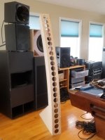
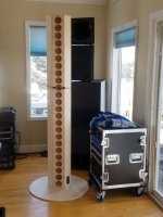
The big circle in the attached pict is for free standing straight. I'm making a big elliptical base for the CBT. And I still have to make a straight base for corners, where the room's base and show molding won't let the box snug to the wall. Oh, and straight box needs a handle(s) like a PA box.
I'll be glad to get the boxes done and painted so I can move on to assembling the driver baffles.
A few iron out details remain...
Perhaps the biggest...despite a lot of searching, I still haven't found a gasket/sealing idea for the TC9's (used front mounted).
Any easy recommendations welcomed !
Projects are going pretty smoothly.
The only real surprise has been how much more difficult the straight corner box has been to plan, cut, and glue ..than has the CBT. It's hard for me to keep the relatively narrow, 7ft long, pieces for the straight box true all the way thru glue up.
And I must admit, I got a little overly confident/tricky with the interchangeable driver baffle. Ended up missing the baffle width for the straight line by needing to trim 4mm width. Fortunately, I knew to complete the straight box first, as the overall design makes it very easy to trim the CBT's width to fit the baffle. It does look like the removable baffle is going to work fine...I got lucky I think
I needed to slow down and figure out removable base plates, to get the proper t-nuts or inserts into the boxes' bases before assembly.
The big circle in the attached pict is for free standing straight. I'm making a big elliptical base for the CBT. And I still have to make a straight base for corners, where the room's base and show molding won't let the box snug to the wall. Oh, and straight box needs a handle(s) like a PA box.
I'll be glad to get the boxes done and painted so I can move on to assembling the driver baffles.
A few iron out details remain...
Perhaps the biggest...despite a lot of searching, I still haven't found a gasket/sealing idea for the TC9's (used front mounted).
Any easy recommendations welcomed !
Attachments
Good to see progress. For a gasket you could use neoprene. I have found it in convenient width for these purposes on ebay. Another option could be something like 3M caulk. I have used that to seal back lights on my old car but also have used it as a pliable gasket for speakers. Butyl rope could work to but is even more sticky.
I'd use the neoprene in baffle width size. Just cut the driver holes and use the neoprene as seal, ideal for a slightly bent baffle. Make sure not to put too much pressure on that driver frame. I'd use rubber rings to fill the arc for the CBT. The neoprene will fill the gap(s).
I'd use the neoprene in baffle width size. Just cut the driver holes and use the neoprene as seal, ideal for a slightly bent baffle. Make sure not to put too much pressure on that driver frame. I'd use rubber rings to fill the arc for the CBT. The neoprene will fill the gap(s).
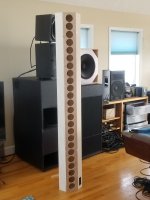
Happy to report the straight/CBT line array project made first sound yesterday. (It slowed down a little because I spent 5 days going to a Rational Acoustics class for making measurements with Smaart..wonderful experience.)
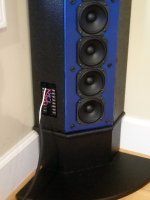
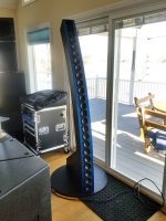
Anyway, I put the first finished driver baffle into a straight-line box, with a base for corner placement.
The Murphy clone seems like the simplest way to begin learning about the arrays, as no shading or delay are involved.
Fired it up with all 24 drivers hooked together to provide about a 5 ohm load. All seems to be working well Played with a little high and low shelving, but nothing else yet. Gonna finish all the boxes and the second driver baffle before any further tuning.
I'm already loving the terminal strip breakout for driver connections, which has ended up with connections for 6 groups of 4 drivers each. It's so easy to change configurations....
Decided to try o-rings for sealing the drivers to the baffle. Made them out of 1/16th o-ring cord. Mounting the drivers and wiring them has been easier than I expected, yay!
May get a CBT version fully done today.
Can't wait to measure these things and start tuning..
Anyway, I put the first finished driver baffle into a straight-line box, with a base for corner placement.
The Murphy clone seems like the simplest way to begin learning about the arrays, as no shading or delay are involved.
Fired it up with all 24 drivers hooked together to provide about a 5 ohm load. All seems to be working well
Played with a little high and low shelving, but nothing else yet. Gonna finish all the boxes and the second driver baffle before any further tuning.I'm already loving the terminal strip breakout for driver connections, which has ended up with connections for 6 groups of 4 drivers each. It's so easy to change configurations....
Decided to try o-rings for sealing the drivers to the baffle. Made them out of 1/16th o-ring cord. Mounting the drivers and wiring them has been easier than I expected, yay!
May get a CBT version fully done today.
Can't wait to measure these things and start tuning..
Attachments
Thx nc535, wesayso !
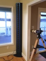
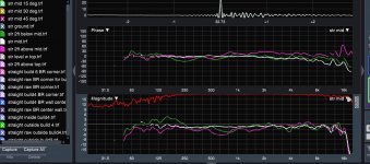
True to my often stated outdoor tuning preference, I took the straight line outside yesterday and made a first stab at measuring and tuning.
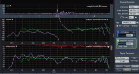
The first graph below is raw response (blue), and then tuned response in green.
Tuning goal was flat mag and phase using 2300 taps of FIR. I really needed quite a few more taps down low, but the 2300 setup made for a very handy first try.
So far, I'm not sure anything can smooth the high end above 8kHz....lots of interactions going on up there...as in 24 drivers worth LoL.
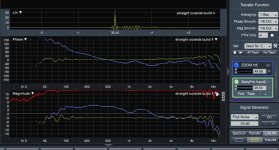
Second graph is the tuned response (now green obviously)
and its measured response (light purple) in a room corner that has 8ft ceilings.
I've tried putting the speaker in the corners of a few different rooms. At this point I'm not so sure what to think about the clear number and size of the interactions with the corner walls. I'll probably try freestanding moving out of the corners some, and maybe in the middle of walls next.
True to my often stated outdoor tuning preference, I took the straight line outside yesterday and made a first stab at measuring and tuning.
The first graph below is raw response (blue), and then tuned response in green.
Tuning goal was flat mag and phase using 2300 taps of FIR. I really needed quite a few more taps down low, but the 2300 setup made for a very handy first try.
So far, I'm not sure anything can smooth the high end above 8kHz....lots of interactions going on up there...as in 24 drivers worth LoL.
Second graph is the tuned response (now green obviously)
and its measured response (light purple) in a room corner that has 8ft ceilings.
I've tried putting the speaker in the corners of a few different rooms. At this point I'm not so sure what to think about the clear number and size of the interactions with the corner walls. I'll probably try freestanding moving out of the corners some, and maybe in the middle of walls next.
Attachments
Mark,True to my often stated outdoor tuning preference, I took the straight line outside yesterday and made a first stab at measuring and tuning.
So far, I'm not sure anything can smooth the high end above 8kHz....lots of interactions going on up there...as in 24 drivers worth LoL.
Looking great!
Top octave looks "good enough", a little ripple never hurt anyone ;^).
What was the microphone height and distance to the line in your outdoor measurements?
Did you save any traces done at varying mic heights?
Try any measurements with the line above "meat bag" height ?
Have the drivers and cut shells for a pair of (stackable) 6 driver TC9 lines, but don't know when I'll get around to all the hard work- your posts are an inspiration!
With your ease of hooking up drivers, it would be interesting to see the results of various line lengths measured under the same conditions.
Art
Nice clean impulse outdoors. Not so nice indoors. Where do all those spikes on the IR come from, the speaker or the room?
You can compare your measurements with those of ra7 published in his thread. As I recall, his dips were as deep for what that is worth.
I think the impulse ripples after the peak impulse come from two causes...
first, the multiple drivers as per ripple seen outdoors. The ripples peaks are about 0.07ms apart. The impulse you see posted is just Smaart's quicky live IR. Better measurements are from the fullblown IR measurement section. I need to study them before any real conclusions, though.
second, I think the multiple drivers' outdoor ripple gets amplified when put in a corner.
Indoors, I tried driving just one block of 4 drivers and impulse really cleaned up vs all 24. I then took a pillow and tied it in front of 3 of the 4 drivers...even further cleanup (as we would expect I guess)
Do you have a link to the thread ra7 posted measurements in? thx
Mark,
Looking great!
Top octave looks "good enough", a little ripple never hurt anyone ;^).
What was the microphone height and distance to the line in your outdoor measurements?
Did you save any traces done at varying mic heights?
Try any measurements with the line above "meat bag" height ?
Have the drivers and cut shells for a pair of (stackable) 6 driver TC9 lines, but don't know when I'll get around to all the hard work- your posts are an inspiration!
With your ease of hooking up drivers, it would be interesting to see the results of various line lengths measured under the same conditions.
Art
Thank you Art !!
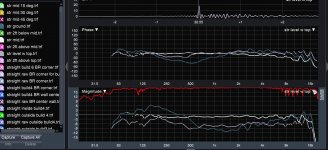
I've been making measurements at only about 4m, since this is an indoor project mainly. Line is about 81" tall.
I've attached a few plots..
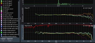
First is mic at mid (white trace) of line, and at plus 2ft from mid, and down 2ft from mid.
Second is mid again, with mic on ground, and even with top of line.
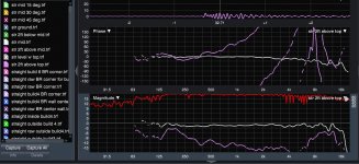
Third is mid again and mic 2 ft above top of line. Couldn't even find an impulse peak haha
Last are some quick horizontals with mic at mid....15, 30, and 45 deg off-axis.
Sorry for not including trace colors in the above descriptions...hopefully it's easy enough to glean from trace panel.
Attachments
Do you have a link to the thread ra7 posted measurements in? thx
Corner Floor-to-Ceiling Line Array Using Vifa TC9
Thx...i remembered reading the entire thread...now i see why i couldn't find it again...it's in multiway
Corner Floor-to-Ceiling Line Array Using Vifa TC9
This page has some measurements at varying heights, distances, etc. Cool stuff, Mark. I haven't been following, but I'll try to peep in every now and then.
Are you going to compare curved versus straight? That'd be fantastic. Without reading through the entire thread, do you have a post where I can read about your drivers, goals, etc.?
One thing I would try is the 'expanding array' design. Basically, as you move towards the center of the array, you taper off the HF response of the individual units. For example, the whole array is providing output at 500 Hz, but by 1000 Hz, it is only the central half, then by 2000 Hz, it is the central quarter, and then higher up, maybe it can be just one driver, which can then be either a waveguided tweeter or a ribbon to control vertical directivity. This way you get constant directivity plus you don't get the combing at HF. It might also be easier to EQ in a room, I don't know. Basically follows this design:
Snell Acoustics XA Reference Tower loudspeaker | Stereophile.com
I tried to do something similar:
Corner Expanding Line Array with KEF Q100
I feel like I didn't give this one enough of a chance to succeed. But would be interesting to see what you come up with, especially because it looks like you have control over groups of units and what they are fed. The tapering is based on wavelength and distance. As the distance between the ends of the operating drivers approaches the wavelength of the frequency, you begin the taper.
Last edited:
Corner Floor-to-Ceiling Line Array Using Vifa TC9
This page has some measurements at varying heights, distances, etc. Cool stuff, Mark. I haven't been following, but I'll try to peep in every now and then.
Are you going to compare curved versus straight? That'd be fantastic. Without reading through the entire thread, do you have a post where I can read about your drivers, goals, etc.?
One thing I would try is the 'expanding array' design. Basically, as you move towards the center of the array, you taper off the HF response of the individual units. For example, the whole array is providing output at 500 Hz, but by 1000 Hz, it is only the central half, then by 2000 Hz, it is the central quarter, and then higher up, maybe it can be just one driver, which can then be either a waveguided tweeter or a ribbon to control vertical directivity. This way you get constant directivity plus you don't get the combing at HF. It might also be easier to EQ in a room, I don't know. Basically follows this design:
Snell Acoustics XA Reference Tower loudspeaker | Stereophile.com
I tried to do something similar:
Corner Expanding Line Array with KEF Q100
I feel like I didn't give this one enough of a chance to succeed. But would be interesting to see what you come up with, especially because it looks like you have control over groups of units and what they are fed. The tapering is based on wavelength and distance. As the distance between the ends of the operating drivers approaches the wavelength of the frequency, you begin the taper.
Hi ra7, thanks for the kind words and info.
Somehow I missed the measurements page you linked from your TC9 array thread, when I was reading up and debating with myself whether or not to do this project. I just downloaded your measurements...very well done !!
It was your project and wesayso's (along with a few other nice folks) that led me to go with TC9's too. Plus I needed to keep cost down because my real design goal has been more about building a platform to learn from than trying to build a new reference speaker. I'm really happy soundwise with several 4-way designs that are built around bms coax CDs and strong subs. I will be surprised, but also completely delighted, if either of the line array types become my preferred sound. So I have big learning goal, iow.
Yes, I definitely plan to compare the curved vs the straight-line. Almost side-by-side so to speak. Hope to be doing that by the end of the coming week.
The 'expanding array' concept sounds interesting and pretty straightforward. I'll try it. Also intend to try delaying the straight line in an arc focused to various distances. With the current wiring setup, I have 6 groups of 4 drivers, and very easy dsp/amp control over each of the groups.
Gonna go study your measurements now, thx again
- Status
- This old topic is closed. If you want to reopen this topic, contact a moderator using the "Report Post" button.
- Home
- Loudspeakers
- Full Range
- Line array steering ?