Yes, I was using a case of it as a PA horn set on poles high above audience for more reach. You have to turn on room reflections and boundaries for that to be used though. It's useful to make it high at first to reduce floor bounce effects them add a more realistic height later. That is why I have back wall at 5000 inches.
Oke, I have tryed to get things in autocad like the table from sheet, can you tell me how? because a tekst based one do not work, but have to say autocad i am not yet used to.
regards
kees
I did not use Autocad. I pulled out data points every 25mm axial distance and plotted in graphing program. Then I over-layed a 2point spline function to approximate tractrix. Then I used the spline to make 3d solid model. Then I unrolled the solid model using sheet metal function to get the 2d cut plan. Kind of complicated but gave me a perfect pattern.
Last edited:
If interested my feedback sound clips. My view "tractrix-0.7x-3" verse "tractrix-0.7x-4" did a difference, the new one not so "hard in face reproduction". My mood still prefer the more soft and as i feel more natural sound percieved from bigbrother ""Tractrix-CLD-clip-04".
I did not use Autocad. I pulled out data points every 25mm axial distance and plotted in graphing program. Then I over-layed a 2point spline function to approximate tractrix. Then I used the spline to make 3d solid model. Then I unrolled the solid model using sheet metal function to get the 2d cut plan. Kind of complicated but gave me a perfect pattern.
Hmm, I ask volvotreter for it.
Hornresp also can do in tractrix mode.
regards
kees
If interested my feedback sound clips. My view "tractrix-0.7x-3" verse "tractrix-0.7x-4" did a difference, the new one not so "hard in face reproduction". My mood still prefer the more soft and as i feel more natural sound percieved from bigbrother ""Tractrix-CLD-clip-04".
Thanks for the feedback - makes sense what your perceived because I put a deep notch to flatten the big 12khz peak. The big driver and horn sound better I agree.
for the low end, I did found this thing.
http://www.kvalsvoll.com/Designs/T138/T138_flyer.pdf
Kvalsvoll Design AS Compact Subwoofer Design Article
regards
http://www.kvalsvoll.com/Designs/T138/T138_flyer.pdf
Kvalsvoll Design AS Compact Subwoofer Design Article
regards
Hmm, I ask volvotreter for it.
Hornresp also can do in tractrix mode.
regards
kees
Volvotreter has several ready to go plans all drawn out already. You may just want to go with those, then modify it with a bass injection port.
Thanks for the feedback - makes sense what your perceived because I put a deep notch to flatten the big 12khz peak. The big driver and horn sound better I agree.
Now lets say that even when 0,7x model gets tested with the new driver that it's designed for, the big still ends up best sound performance probably because the use of better and more expensive driver. Would it be possible by more cost to mount and use the PRV driver on the 0,7x model to have more friendly size horn for home use and thereby lift up sound performance.
Now lets say that even when 0,7x model gets tested with the new driver that it's designed for, the big still ends up best sound performance probably because the use of better and more expensive driver. Would it be possible by more cost to mount and use the PRV driver on the 0,7x model to have more friendly size horn for home use and thereby lift up sound performance.
The Bruce Edgar tractrix indeed used the same size horn with a 5in driver. I fear that coupling a 5in driver into a 2in throat will cause a low pass band pass effect and cut off HF's. I have thought of trying it though. If you are good with 400Hz on the bottom and 8khz on top I think that is where it will end up at with the PRV driver.
Maybe I will stick the 5MR450NDY into the 0.7x scale later today and see what happens.
")
Last edited:
5MR450NDY in 0.7x vs 1.0x comparison
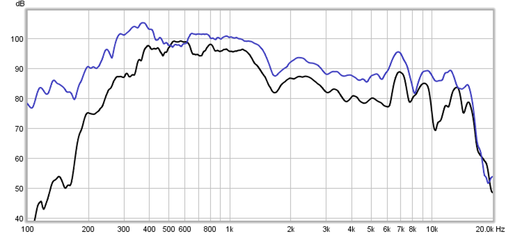
Here is raw response of the 5MR450NDY in the 1x(blue curve) vs the 0.7x (black curve). The drive levels are different as are the HPF settings. However, trends are there and you can see that they are similar with the 0.7x having more attenuation of the HF content, and it exhibits more harsh peakiness above 6kHz and big dip at 10kHz. Also, the low end reach on the 1x is 300Hz and 400Hz on the 0.7x. It could probably made to work.
Here is raw response of the 5MR450NDY in the 1x(blue curve) vs the 0.7x (black curve). The drive levels are different as are the HPF settings. However, trends are there and you can see that they are similar with the 0.7x having more attenuation of the HF content, and it exhibits more harsh peakiness above 6kHz and big dip at 10kHz. Also, the low end reach on the 1x is 300Hz and 400Hz on the 0.7x. It could probably made to work.
Attachments

Nice is it wrong mayby expect some pretty good response when you do some tactical clever DSP EQ'ing. If you later on intend digging deeper be nice viewing EQ'ed plots and listening a soundclip.
By the way, going your footstep just received 2 times Vifa and Dayton UMM-6 microphone. I ordered from German webshop where they titled Vifa 9BN119/8, delivered devices titled Peerless TC9FD18-08, but looks like right thing. I hold a Dayton DATS unit that can measure and produce impedance plots + TS parameters. If interested i can post plots on two newly unpacked Vifa's.
By the way, going your footstep just received 2 times Vifa and Dayton UMM-6 microphone. I ordered from German webshop where they titled Vifa 9BN119/8, delivered devices titled Peerless TC9FD18-08, but looks like right thing. I hold a Dayton DATS unit that can measure and produce impedance plots + TS parameters. If interested i can post plots on two newly unpacked Vifa's.
This is tempting example can't believe you get it to reproduce so low http://www.diyaudio.com/forums/full...vifa-curvy-cabinet-dcr-tc9fd.html#post3849406.
Both Vifa's impedance and TS data taken by DATS unit:

This also tempting because last couple of years been reading about those running DSP where they correct every small response details in minimum phase domain by IRR, thereafter a FIR for linearizing phase too and resulting in possibility for speaker to reproduce squarewaves think around 100-5500Hz area. Like to try if possible with a FAST system and have a listen what comes out, seems i have all the tools laying around me now after getting UMM-6 and Vifa's.
It's not simple setup but could try by using JRiver, Rephase, REW, UMM-6, FAST system with 2 x sealed Vifa TC9FD-18-08 for HF and 2 x sealed 10" Monacor SPH-250KE for LF.
Both Vifa's impedance and TS data taken by DATS unit:
This also tempting because last couple of years been reading about those running DSP where they correct every small response details in minimum phase domain by IRR, thereafter a FIR for linearizing phase too and resulting in possibility for speaker to reproduce squarewaves think around 100-5500Hz area. Like to try if possible with a FAST system and have a listen what comes out, seems i have all the tools laying around me now after getting UMM-6 and Vifa's.
It's not simple setup but could try by using JRiver, Rephase, REW, UMM-6, FAST system with 2 x sealed Vifa TC9FD-18-08 for HF and 2 x sealed 10" Monacor SPH-250KE for LF.
Last edited:
I was wondering when someone would do the Viva la Vifa DCR. Those speakers sound excellent and the bass is indeed very deep but the sound levels are not for a large room. Works great in a smaller room like office or bedroom. I had them in my office at work but neighboring office mate complained that there was too much bass vibration like I had a subwoofer or something.
If you want to do the whole FAST thing, give miniDSP a try and get some cheap tpa3116d2 amps. Look at new Sure boards - I have heard they sound very nice stock. I went down the path of desiring FIR too. Save that for your reference system someday. For now it is a lot more practical and fun to experiment with IIR filters as they an be changed in real time. The FIR requires you to use IIR first then separate math to generate FIR equivalent.
The sealed boxes you suggest are good ideas, try the Nautaloss if you go that way.
Btw, your Vifa's measure very well - you have some nice lower fs units. Mine measured at 125hz.
Last edited:
I have a little question.
Enclosure 'Low Rear Chamber' Node=70 Vb=40L Lb=20cm
Driver 'Low Driver A' Def='LowDriver' Node=30=31=70=71
Duct 'Low Throat Chamber A' Node=71=73 dD={Lc_Dia} Len={Lc_Len}
Duct 'Low Port A1' Node=73=130 dD={Lp_Dia} Len={Lp_Len}
Driver 'Low Driver B' Def='LowDriver' Node=31=0=70=72
Duct 'Low Throat Chamber B' Node=72=74 dD={Lc_Dia} Len={Lc_Len}
Duct 'Low Port B1' Node=74=130 dD={Lp_Dia} Len={Lp_Len}
Duct 'Rear Tap 1' Node=70=140 dD={Rt_Dia} Len={Rt_Len}
Duct 'Rear Tap 2' Node=70=140 dD={Rt_Dia} Len={Rt_Len}
Waveguide 'WG1'
how are the speakers connected? serial or paralell.
I think I get slowly understand akabak a little, special when I have examples, it is quite readable.
this here I see that the low port input and low tap are on the same distance? like on left and one right of horn .
| Define Horn Segment Areas
areaSegment1 = 0016.00e-4; |Comp Driver input (sq cm)
areaSegment2 = 0106.92e-4; |Mid Port input (sq cm)
areaSegment3 = 0957.90e-4; |Low Port input (sq cm)
areaSegment4 = 0957.91e-4; |Low Tap input (sq cm)
areaSegment5 = 2222.18e-4; |Horn Mouth before flare(sq cm)
areaSegment6 = 4379.79e-4; |Horn Mouth after flare(sq cm)
here some sim from the phillips, I have drop the mids because I want
two way, I go for conic horn with a tweeter driver..
See a fase shift at 800 a 900 hz cancel the sound off, I did also see phillips
like closed back more then port support. Also the extra flare on the edge of the synergy horn do give for me a more badly response (peak on 800 hz.) do
not now why because it has to smooth out, not for all speakers i think.
here I have the inspiration from.
mike.seddon.ca - Horn Modeling
regards
kees
thanks.
Attachments
Kees,
Thanks for the Mike Seddon synergy build link. His AkAbak script is a good example and you can see what he was doing as it is well commented. That is an awfully complex box compared to having a fullrange handle 300Hz to 15kHz and then adding a couple of woofers. Those mids with 8 ports and tight mounting look particularly painful to implement. Getting the XO right between the mids to HF can be tricky. Seeing how much work is involved I think the DSL SH50 is a good bargain at $8000/pair considering they have 9 drivers a piece and a well designed passive XO.
Regarding wiring your woofers: you can do series or parallel depending on what your amplifier can handle. If you wire in parallel and assuming these are 8ohm drivers and your amp can handle 4ohms, you get a +6dB sensitivity boost (at same drive voltage). Just make sure they are in phase.
Last edited:
Kees,
Thanks for the Mike Seddon synergy build link. His AkAbak script is a good example and you can see what he was doing as it is well commented. That is an awfully complex box compared to having a fullrange handle 300Hz to 15kHz and then adding a couple of woofers. Those mids with 8 ports and tight mounting look particularly painful to implement. Getting the XO right between the mids to HF can be tricky. Seeing how much work is involved I think the DSL SH50 is a good bargain at $8000/pair considering they have 9 drivers a piece and a well designed passive XO.
Regarding wiring your woofers: you can do series or parallel depending on what your amplifier can handle. If you wire in parallel and assuming these are 8ohm drivers and your amp can handle 4ohms, you get a +6dB sensitivity boost (at same drive voltage). Just make sure they are in phase.
Hi
What concerns the serial or paralell conection of the woofers it is only the akabak where I did ask for how to node this.
I have not interesting in a three way box, but two way, the sim you see is with mid,s removed and the phillips x 2 woofer in stead of the big 12 inchers who are first.
The extension of the phillips woofers go above 1 khz and there I go put a tweeter not a CD.
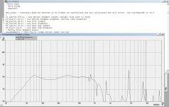
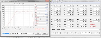
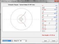
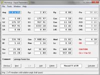
here are some sims from hornresp who can fine with conic flare horns, see the nice plot, but i still not understand the ATC well, this cross sectional in cm2 is 557 devided by two and 0.448 liters for the woofers who is X two.
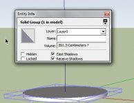
It looks so big when put that cut out circel in sketchup and calculate the square cm it is much lower then it is in hornresp, I do something whrong not now what it is, cc and cm2 on that place is confusing..
What concerns your design, I have to see how to make the horn first, the little visatons are a nice candidate, but I need to decide what I do now get to much at once confuse me, I ma afcourse a amp designer not box.
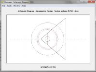
Hronresp input is from Mike Seddon, I have change some things for the plot, woofers going from 80 to 1100 hz. port is 7.5 cm from throat.
regards
kees
Attachments
Last edited:
In AkAbak the driver nodes are specified as 'voltage source'='voltage drain'='front diaphragm node'='rear diaphragm node'
With node 1 default as amp source and 0 as ground.
For two drivers in parallel wire like this:
Driver 1
Node=1=0=10=11
Driver 2
Node=1=0=12=13
Assuming 10 and 11 are driver cone chambers and 11 and 13 rear chambers of each driver
For serial wiring
Driver 1
Node=1=2=10=11
Driver 2
Node=2=0=12=13
So current from amp goes into positive terminal of driver 1 and to connector node 2 which is then positive terminal of driver 2.
Hope that helps.
- Home
- Loudspeakers
- Full Range
- PRV 5MR450-NDY for FAST/WAW applications