Some more input from my research on this spark generator. The internal supply charges the cap to approx 500V before discharge. Anything smaller than about .2 uF and it doesn't charge all the way and doesn't work.
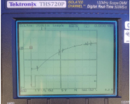
With this arrangement and 500K Ohms (5 100K in series) I get a peak voltage before breakdown of about 6 KV. It takes about 60 uS to charge and nanoseconds to discharge the stored charge. Its now definitely a single discharge.
Getting a good current reading is quite hard. The current into the 500K is about 500 mA. I suspect the current at the discharge is higher. I'm using about 4' of RG59 to transport the voltage to the spark gap. Out of the generator there are two HV wires which is not good for EMI. I'm going to replace this with a single coax all the way to the spark gap. I hope that reduced the radiated noise.
So, with a coax from the coil to the gap. Put the spark gap in a metal can and I still get EMI on the scope once I connect probes. Att a 100Meg resistor in series at the coil end and it still sparks and still EMI. Less at least. This is a really good EMI source.
Distance helps, however the active circuitry in the power supply gets a big DC shift with the spark and starts to return but is still offset when the acoustic pulse hits. I will switch to a different power supply and see if that helps. My hopes for this are dimming fast.
Distance helps, however the active circuitry in the power supply gets a big DC shift with the spark and starts to return but is still offset when the acoustic pulse hits. I will switch to a different power supply and see if that helps. My hopes for this are dimming fast.
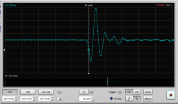
This shows the EMI problem. Upper trace- microphone. Lower trace trigger from spark generator
Holds true with two power supplies/buffers. When the spark happens there is a big DC shift that takes a long time to recover. The acoustic pulses are near the center.
I may need to abandon this and revert to using a ribbon tweeter or electrostatic actuator when possible. I'll keep thinking about this in any case.
Attachments
I made it work by using ring cores and ferrite beads everywhere. Rings cores on the HV wires help, as well as individual beads for the + and - output wires, both near the gap and at the coil.
My battery powered sparkers do not need to be plugged in, so the area they can radiate in can be confined to a small area using a relay to isolate a remote trigger.
Any wires leaving the spark generator needed to be capacitively or inductively isolated.
My battery powered sparkers do not need to be plugged in, so the area they can radiate in can be confined to a small area using a relay to isolate a remote trigger.
Any wires leaving the spark generator needed to be capacitively or inductively isolated.
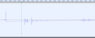
After some more fiddling here is what I get recording. The emi pulse is the first transient. The DC offset starts there. The two acoustic pulses are due to a reflection, the first is the more valid one. I found that despite the full isolation of the channels in the Tek connecting the sync makes for a big dc issue on the other channel. Disconnecting it seems to remove the DC, at least on the scope. Still seems there on the recording setup. Enough for today.
Attachments
I think this spark generator just makes too much EMI. I have ferrites etc. all over. The coax was to make the radiating window smaller. I have isolated from the AC line. The scope and the mike are both battery powered. I even get stuff on the scope with the input shorted.
I have been dealing with this stuff testing surge strips for years. I think its the current peak that makes the most trouble. I have a 100 Meg resistor in series inside the connection to the HV terminal in the coil and it still has too much energy. However this is a 12V coil getting hit with 400 V. Maybe I need a different coil 20:1 instead of 2000:1? The discharge is using the stored charge in the coax (8' of RG59) as part of its energy, Maybe all of it with the 100 Meg series resistor, unless that's arcing inside. I'll check it. If it is the terminal resistance will have changed.
I have been dealing with this stuff testing surge strips for years. I think its the current peak that makes the most trouble. I have a 100 Meg resistor in series inside the connection to the HV terminal in the coil and it still has too much energy. However this is a 12V coil getting hit with 400 V. Maybe I need a different coil 20:1 instead of 2000:1? The discharge is using the stored charge in the coax (8' of RG59) as part of its energy, Maybe all of it with the 100 Meg series resistor, unless that's arcing inside. I'll check it. If it is the terminal resistance will have changed.
The coil looks like an automotive coil, but now I wonder. Surely 400V into a 12V coil would fry the secondary insulation in no time. Maybe it is custom wound by a factory that makes the standard kind.
I suspect it is arcing through the resistor, and I wouldn't assume that it will be noticeable in the resistance value.
The corner frequency of 100Mohm and 130pF is 12Hz, there is no way the 100Mohm resistor could charge the coax fast enough to reach sparking voltage.
I suspect it is arcing through the resistor, and I wouldn't assume that it will be noticeable in the resistance value.
The corner frequency of 100Mohm and 130pF is 12Hz, there is no way the 100Mohm resistor could charge the coax fast enough to reach sparking voltage.
I went back at this today. Made some changes.
1) 100K at the coil going into the coax.
2) switching around the output of the preamp poser supply.
Those two changes got the EMI down a lot, to the point I can make OK measurements. The 100 Meg resistor is now 88 Meg, definitely arcing. The 100K seems to handle the stress. Its a 2W size.
Now that I can make an OK recording its time to figure out the acoustics for a decent measurement.
@keantoken, could you do me a quick favor and paraphrase how the software you are using computes the impulse from the doublet. I found some very interesting discussions (some even from when FORTRAN was the only scientific programing choice) that claim integrating a sampled waveform is a far harder problem than it seems. To me it looks like that if you want only the phase it should be easy.
Last edited:
DIYAudio stopped sending me updates to this thread for no apparent reason.
It revolves around Sox and it's capabilities. Internally it is 32 bit integer. So if I hipass too aggressively for trigger conditioning and then correct afterwards, I get troublesome bit noise at LF. Averaging helps with this.
For integration I use a 200Hz lowpass filter centered at 1KHz, so the impulse SPL at 1KHz is the same as in the raw doublet. When testing with white noise and a synthesized doublet, the lowpass filter is flat to 70KHz or so. So it didn't seem to be a problem and the variation could be calibrated out.
I can't figure out where the processing for lowpass, higpass or bass filters happens, but it would be somewhere in here:
SoX - Sound eXchange / Code
/ [42b355] /src
I would guess that those filters are all different forms of a DFT filter as in dft_filter.c.
I'm making more progress in sorting out what to tweak to get a good recording free of EMI and extra pulses.
First- the gap. It needs to be large enough that the ringing after the initial discharge doesn't also discharge.
Second some tweaking of the coax and its not radiating anywhere near as much emi. I have the 100K feeding to coax, and 100pF 50 Ohm RC at the coil end of the cable to ground and a series 50 Ohm at the spark.
switching back to the battery supply and carefully managing the connections seems to have removed the hum pickup for now.
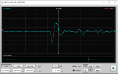
Here is the acoustic waveform I'm getting. Tomorrow I'll try to setup to do a reasonable first pass acoustic setup with the current spark. I still have stuff like mike stands. clear space etc. to deal with and the first shot will be really compromised but its a start.
Would it be possible to generate a "calibrate" file in REW that could do the integration?
First- the gap. It needs to be large enough that the ringing after the initial discharge doesn't also discharge.
Second some tweaking of the coax and its not radiating anywhere near as much emi. I have the 100K feeding to coax, and 100pF 50 Ohm RC at the coil end of the cable to ground and a series 50 Ohm at the spark.
switching back to the battery supply and carefully managing the connections seems to have removed the hum pickup for now.
Here is the acoustic waveform I'm getting. Tomorrow I'll try to setup to do a reasonable first pass acoustic setup with the current spark. I still have stuff like mike stands. clear space etc. to deal with and the first shot will be really compromised but its a start.
Would it be possible to generate a "calibrate" file in REW that could do the integration?
Attachments
First- the gap. It needs to be large enough that the ringing after the initial discharge doesn't also discharge.
This is what I did early on, but damping the coil has so many advantages. If you actually need a large spark though the damping may be unnecessary for this reason.
Would it be possible to generate a "calibrate" file in REW that could do the integration?
This is one of the first things I tried, but every program has some variation near Fs/2. I settled on doing it in sox because that allows me to cull noises and get useful data like scatter plots. My script does output the raw doublets but I may need to update that part of the script.
One way to get the response without any integration would be to use a .frd file in REW that is just a SPL=f line. REW can just divide the response. You can also set it as the default calibration file.
Here is a suitable .frd file, centered at 1KHz=0db. You can set this as your default calibration file in REW and it will automatically load for any doublets you import. Or you can manually load it as the calibration for your doublets.
In theory, the step response could be exported to convert the doublet into an impulse, but there is no option in REW to export the step response. Might be worth discussing with the REW dev.
Attachments
How are you viewing the doublet in ASIO with the correction? This was just to use as a calibration file in REW. If you are using it for a DSP program, you will get that program's integration errors. That is the whole point of performing the correction on the response curve instead of the doublet.
That does look like your doublet would look like lowpassed. There is peaking in the response which is why it still looks like a doublet after integration.
That does look like your doublet would look like lowpassed. There is peaking in the response which is why it still looks like a doublet after integration.
I checked and REW treats the cal file correctly EXCEPT for in the scope function. Not too surprising since translating a frequency response correction to a time correction is not simple. Tek charges thousands for that feature in their premium scopes.
Let me see if there is a way to implement that as an EQ in Reaper. I gave up on Audacity because of no ASIO support and its was not working right with the internal windows sound engine.
Let me see if there is a way to implement that as an EQ in Reaper. I gave up on Audacity because of no ASIO support and its was not working right with the internal windows sound engine.
- Home
- Design & Build
- Equipment & Tools
- Spark calibration of microphones