I leave soon for long road trip and won't be much help for a day or two.
I'm sorry for continuing troubles. Post #41 sure sounds like failed opamp as no negative voltages nearby. Hot IC also a mystery as so many current limiting resistors surround.
Have you doubled checked IC socket solder work? And double check IC orientation. Please don't take offense. I've installed ICs backwards myself--- and more than once.
Bye for now and good luck!
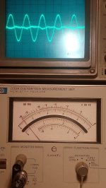
Well, the HP339A is working great again 
here I ajusted the analyzer to a sweet spot, at 1KHz (10x 100), 1.7Vpp, and GND lift, resulting in a residual distortion of -100.5dB, or about 0.0009% (dominated by a residual of the fundamental, some 2nd harmonic and noise).
Thanks you guys. not only did I get my HP339A working, but I also learned alot about fault finding!
Have a great new year!
Attachments
Managed to get it to 0.0005% (-106dB) with the KH-4400a after replacing two LM318 opamps at U125 (main oscilator opamp) and U183 (output buffer) in the KH-4400a,with opa134, and carefull adjustment of the THD trimpot.
On my computer sound interface, a Focusrite Saffire 26 I/O, I measure -108dB for both the HP339A internal oscilator and the KH4400a. Guess I am hitting the limmit of the HP339a distortion analyzer at -106dB.
On my computer sound interface, a Focusrite Saffire 26 I/O, I measure -108dB for both the HP339A internal oscilator and the KH4400a. Guess I am hitting the limmit of the HP339a distortion analyzer at -106dB.
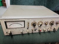
I've got a somewhat similar issue. Picked up a 339A in shocking condition (top and bottom are also dented and no feet) but it will power up.
I've got a Picoscope 2204A which will do THD to ~ 50dB and wanted more (silly me, I sold a Marconi destortion meter about 5 years ago - was working properly but the frequency control was hard to move - seized up potentiometer, grease dried out).
Anyway the meter will not null properly.
Opening the unit showed a crudely replaced input fuse (bad soldering).
The ground connector for the monitor has been replaced, therefor the front has been off. Have not investigated if there are markings on the wafers when the shafts came out when the front was taken off.
Picoscope indicates that the oscillator is running, not as stable as I would like from my HAM radio days but still acceptable imho. Unfortunately the frequency is a little low: 1Khz setting is more like 960 - 970 Hz.
When feeding a signal from the Picoscope to the analyzer I get a "null" at approx 1040Hz but both Hz lights are ON ???? From the manual I was under the impression that when a lock happened they would be OFF?
Changing the 10, 100, 1K and 10K freuency multiplier changes the behavior of the Hz LED. Sometimes they are not on, or one or the other is on. Similarly the dB scale has some impact on the LED lights behavior(????).
A "null" gives me a distortion level of approax - 34dB whereas the internal THD of the Picoscope registers about -49 ~ -50 dB. Can get a "null" on 10, 100 and 1K multiplier freuency but not on the 10K.
The level and relative level meter seems to work fine.
The output level switch of the oscillator: .1V - 3V works fine but 0.03V and lower don't make a difference to the meter sitting halfway.
Analyzer: when input of analyzer is shorted then at input level setting of 0.3V and higher the analyzer indicates on the -80dB scale -13db, but if the input level is 0.1V or lower then it sits at -3dB.
At the moment the unit is a pain to work on since it has missing knobs and the remainder are nearly all cracked and ready to fall apart.
I'm on the brink of ordering some Elma knobs with some dials and then (like in the old HAM days with a vernier) have a chart stuck to the top of the unit indicating what each position is indicating.
@tschrama (by the way: I'm Dutch by birth): you managed to fix yours, do you feel it was the TL074 that fixed it?
Anyone else who wants to chime in, please do so. Mind is not what it used to be after open heart surgery a few years back and it does not help that I am doing this on a shoe string not having worked since 2000 due to no immune system.
Not that long ago we moved closer to our children because of my health. As a result I will only be working this occasionally since there are chores that have to be done around the home that take precedence. It will be a slow job.
Thanks in advance to any assistance being offered.
AM
Attachments
Last edited:
I'll try to help. Have you downloaded service manuals from the Keysight website?
I'd recommend cleaning the switch contacts, especially if they "feel" erratic when you manipulate the controls.
Does the unit null properly at some frequencies?
The Elma knobs look interesting. I'll be interested in your results.
Steve
I'd recommend cleaning the switch contacts, especially if they "feel" erratic when you manipulate the controls.
Does the unit null properly at some frequencies?
The Elma knobs look interesting. I'll be interested in your results.
Steve
Hi,
As Dick Moore (RIP) mentioned over on the long low-distortion oscillator thread these polystyrene knobs were not HP's finest hour. At least you have a functioning knob.
On mine I converted one knob to a chicken head knob, which functions great.
The time consuming thing was reversing the numbering scheme and getting
everything to fit and correct placement in the circle.
You're in good hands as Steve (aka BSST) knows more about this stuff than
I'll ever know.
And Demian (aka 1audio) is one of the last remaining few who knew of the
work with the HP339A over in that long thread, good hands also.
Cheers,
Last edited:
Managed to get it to 0.0005% (-106dB) with the KH-4400a after replacing two LM318 opamps at U125 (main oscilator opamp) and U183 (output buffer) in the KH-4400a,with opa134, and carefull adjustment of the THD trimpot.
On my computer sound interface, a Focusrite Saffire 26 I/O, I measure -108dB for both the HP339A internal oscilator and the KH4400a. Guess I am hitting the limit of the HP339a distortion analyzer at -106dB.
You might be at the Focusrite limit? Depending on what you did with the
HP339A, you can get -15dB better I believe.
I'm tempted to update mine again, but thankfully my Dell laptop fried and I can't do it as the QA only works on that dell.
Cheers,
I'll try to help. Have you downloaded service manuals from the Keysight website?
I'd recommend cleaning the switch contacts, especially if they "feel" erratic when you manipulate the controls.
Does the unit null properly at some frequencies?
The Elma knobs look interesting. I'll be interested in your results.
Steve
I have downloaded the manual from different places but it looks like I might need to spend $7.50 to get a proper legible schematic on one page as well as the parts list.
Behavior of the switches is indeed eratic, in one position of the distortion switch I thought I got a proper reading when I held the switch pushing to one side.
I am suspious of bad soldering contact between switch and PCB, if I remember correctly there may be some issues with gold plating and soldering. But memory may be faulty, it is a long time ago that I read something about it. Can someone enlighten me on this front?
Still waiting for the invoice to come through for the Elma knobs, the 36mm skirts had sold out so had to resort to the 44mm (top row) and 26 mm (osc. level). Top row will have only abput 1.6mm between skirts which should be enough. It is possible to make a dual concenrtic knob with them just have to select the two that fit properly together. The 9mm was never stocked locally and the 10 mm is alternative but needs some minor surgery to make it fit. (there is a little ridge at the bottom that I'll remove and the it will slide into the top of the 14.5 mm knob with the 26mm dial). The top row has 30 degree steps, the osc. level has 36 degrees. There will be too many numbers on the dials but that is OK, at least I'll know what position the switch is in. Thought about using water decals on the back of blank dials and then give it a coat of some protective paint but frankly that is a lot of work. Can always reconsider later, priority is trying to sort proper functioning out first. May take till next week before I see the knobs which will cost me more than the unit. (rough conversion to USD: approx 40 for the unit) Could not locate an overseas supplier that had the dials and the local distributor is not interested in bringing more Elma dials in. Element14 (previously Farnell) has some knobs but not the dials. Who knows, it may be an obsolete product that I stumbled upon.
My first step would be to look at the distortion residual with the picoscope. There may be a lot of hum or noise dominating the measurements. Then go through the oscillator to get it functioning correctly.
The monitor output appears to have some hum and wanders all over the screen, the oscillator output is clean but frequency is slightly off and wanders about 2 ~ 3 Hz @ 1Khz according to Picoscope. Ofcourse that may be the oscilloscope but I feel it is the oscillator.
I did feed the analyzer straight from the AWG on Picoscope and could not get proper null except a few times when I pushed on the distortion knob to one side.
Steps intended to follow:
1) Wait for invoice and order knobs and wait for those to arrive
2) Clean switches and check carefully for dry solder.
3) Check behavior of switches when fed from AWG on Picoscope and get analyzer to work. May need work on the auto null part.
4) Check/ adjust oscillator synchronisation with auto null.
5) Check/fix monitor output.
6) Address cosmetics
AM
Last edited:
Knobs: Element14 is known in the US as Newark. Elma no longer manufactures the dials according to Newark. Mentor is another brand suggested there that has clear dials and with numbers. But I could not work out which dial would go with what knob. There are still some old stock Elma dials to be found (e.g. noticed some in Switzerland) but shipping costs can be prohibitive. Rotary switches and knobs looks to be another item on the brink of disappearing and to be replaced with push buttons, touch buttons or remote controls.
Last edited:
Hi AM,
What little Keysight offers in online archiving seems to be slowly dissipating. The links below uses to reside together but now only the later-dated manual shows in a straightforward manner.
The early edition (1979) seems to be missing the oscillator schematic but has marginally better legiblity. The 1983 version has the missing oscillator schematic but text quality is even poorer.
If these links don't work, please advise. At least the price (free) is about right.
Good luck!
https://literature.cdn.keysight.com/litweb/pdf/00339-90001.pdf?id=813081
339A Distortion Measurement Set Operating and Service Manual | Keysight
Last edited:
Hi AM,
What little Keysight offers in online archiving seems to be slowly dissipating. The links below uses to reside together but now only the later-dated manual shows in a straightforward manner.
The early edition (1979) seems to be missing the oscillator schematic but has marginally better legiblity. The 1983 version has the missing oscillator schematic but text quality is even poorer.
If these links don't work, please advise. At least the price (free) is about right.
Good luck!
https://literature.cdn.keysight.com/litweb/pdf/00339-90001.pdf?id=813081
339A Distortion Measurement Set Operating and Service Manual | Keysight
Thanks, did not have the 1983 schematic.
While waiting for some paint to dry I had some downtime to play with the 339A and look at the self test section.
I also put the PicoScope to use. The 2204A has a THD capability of approx -50dB ~ -52dB. After warm up and tuning the frequency vernier I am able to get exactly 1Khz. Time to go through the test steps in the manual:
Section 3.49: All parts pass.
Oscillator works fine - Picscope measures all the way down to approx -56dB THD on some frequencies and the worst measurement is -50dB. IMHO this is the limitation of the Picoscope and I'm sure that the oscillator is better than that.
As mentioned before I found a crudely soldered fuse, definitely some not some HP handiwork.
Section 3.51
- g: pass
- h: pass
- j: pass
- k: pass
- l: part pass: works down to 100mV fine (input and output) but below 100mV the analyzer no longer measures correctly. Disconecting the oscillator and measuring on multimeter / oscilloscope indicates the oscillator works fine and all output levels can be adjusted correctly.
But when the oscillator is conected to the analyzer then below 100mV something is wrong: adjusting oscillator output voltage shows a limited range on the analyzer or oscillosope or multimeter. The meter sits just over halfway. Leaving oscillator sitting at 30mV and changing the analyzer input level lower to 30mv, 10 mV, 3mV and 1mV does not move the analyzer meter at all, stays where it is just over halfway.
3.53:
i: meter indicates about -2.4dB
j: meter indicates about -2.8dB on the next range. Next lower keeps meter at same setting and does not move at all regardless of input level settings.
3.54:
e: pass (-3.6dB)
g: pass (-4 db)
i: fail (-5.8dB)
It looks like the lower input levels of the analyzer is not functioning properly.
Knobs have been ordered but wrong ones were shipped. Waiting for these to arrive in order to ship them back.
Last edited:
Great news about frequency accuracy of the oscillator section.
I still advocate a thorough cleaning of switch contacts, but I also like Demian's suspicion of power supply hum--- especially since you mention hum in the monitor output. The 339A has separate supplies for the oscillator and analyzer sections isolated from each other. All supplies should have no visible hum on a scope at highest AC sensitivity. To ensure good supply behavior, all input filters ahead of the +/- 15V regulators should have modest AC ripple and several volts of drop-out headroom.
When you're ready to focus on the input amplitude issue, the symptoms point to the Input board A5. Monitor TP103 with your scope as you manipulate input range switch S4. Because you mention misbehavior at 100mV and below (I'm making a big leap here with scant data), scrutinize especially switch section S4E--- R120 is active at 100mV and below. Section 8-28 has a description of the input section.
Good luck--- you've already made good progress!
- Home
- Design & Build
- Equipment & Tools
- Could use some help repairing my HP 339A