Demian, you are correct. 
Never gave it any thought that it could be HP's part numbers.
Checking the parts list in the 1983 manual (the 1979 one is unreadable) shows it as being the internal HP part number.
Never gave it any thought that it could be HP's part numbers.
Checking the parts list in the 1983 manual (the 1979 one is unreadable) shows it as being the internal HP part number.
HP was notorious for that stuff. You could not tell easily if a part is custom or just HP numbered. There is a cross reference on the net somewhere.
Generally I prefer not to change anything except for known bad parts when reclaiming a mess. Once its working then making changes can be constructive. Before its working you are possibly making new problems and hiding clues for the original problem.
Going through the grounding would make a lot of sense. The symptoms all suggest checking all the internal ground connections and connections to the I/O connectors.
That is a good practise - first get it going so you have a reference.
Making changes to "improve" - I really don't like doing it, far more prefer to use it as designed.
And when making changes then only one at a time. Then use it for a while to ensure nothing has been overlooked during the testing of the change. Often things improve in one area and has an unintended deterioration in another. Output level potentiometer is one thing that will need attention - it is "scratchy" - i.e. value does not change smoothly.
Resurrected
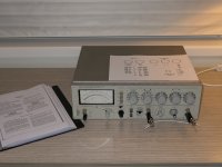
The last of the parts arrived last week and today I had some time to put these in. I found another Bourns potentiometer at Mouser that had the right shaft length, was imperial sized, had solder lugs and fitted straight in. I used even the same nut.
While waiting for the parts I printed out the manual and put it in a display folder.
Found the bad ground - some oxidation on a connecting cable.
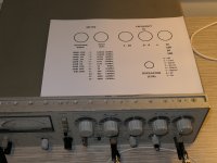
Made a cheat sheet, still have to trim it to size and get it laminated.
Except for a slight adjustment of the frequency everything was spot on so if it works then leave it alone.
Thanks to all who helped.
AM.
The last of the parts arrived last week and today I had some time to put these in. I found another Bourns potentiometer at Mouser that had the right shaft length, was imperial sized, had solder lugs and fitted straight in. I used even the same nut.
While waiting for the parts I printed out the manual and put it in a display folder.
Found the bad ground - some oxidation on a connecting cable.
Made a cheat sheet, still have to trim it to size and get it laminated.
Except for a slight adjustment of the frequency everything was spot on so if it works then leave it alone.
Thanks to all who helped.
AM.
Attachments
Last edited:
Hello All. Could use some help with my 339A too.
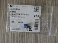
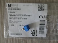
Looking for photomodule 1990-0644 or a replacement for this photomodule.
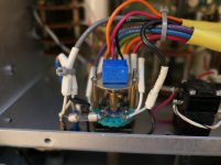
Last summer, was reading through the different threads on this forum and decided I wanted to become member of the 339A club. Did something rather foolish, bought a unit from a website in Israel through Ebay. Got the unit in a very poor packaging, relay was floating around inside the cabinet. Luckily not much visible damage, so decided to keep the unit. Did first a clean up of the unit. Put relay back in position, reconnected cables, fixed screws, checked connectors. Repaired a broken binding post, put in 4 new filter capa's in the power supply and installed the recommended Bourns potentiometer.
First signs after power up (with variac) were promising, unit did seem to work. By now, convinced that the oscillator section is pretty much ok. And the distortion testing did seem to work, especially with the filters on. However, testing the build-in oscillator with filters off yields a reading of -56dB. The residual at the output monitoring is a clear and stable 450KHz signal ... Done some testing with my 331A to ensure the 450KHz is not caused by power line, power supply or the build in oscillator.
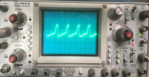
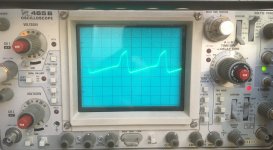
Further testing and measuring shows a very, very unexpected behaviour. The amplitude control is running at a frequency of 450KHz and the regulation is through pulse width ! See attached picture of the signal meausered at R23 (A4 board), scope is at 5V and 1µsec. Believe this is caused by a repair where the photomodule 1990-0644 on the A3 board is replaced with an incompatible photomodule.
And very strange, but this pulse width control seems to work over the complete frequency range, have tested with build-in oscillator frequencies from 100Hz to 50KHz. Slight impact on the noise frequency, varies from 435KHz to 480KHz. Distortion measurement remains about -56dB. During the moment in time where the amplitude control does its work, one can nicely observe how the pulse width is becoming smaller till it reaches stable state.
Anyone seen this before ?
And of course, is there an alternative to replace the faulty photomodule with a correct one ? Or is there a possibility to still find the HP 1990-0644 (as I don't seem to find any trace on the internet).
At this point I am stuck, so any help will be very welcome.
Dirk
Looking for photomodule 1990-0644 or a replacement for this photomodule.
Last summer, was reading through the different threads on this forum and decided I wanted to become member of the 339A club. Did something rather foolish, bought a unit from a website in Israel through Ebay. Got the unit in a very poor packaging, relay was floating around inside the cabinet. Luckily not much visible damage, so decided to keep the unit. Did first a clean up of the unit. Put relay back in position, reconnected cables, fixed screws, checked connectors. Repaired a broken binding post, put in 4 new filter capa's in the power supply and installed the recommended Bourns potentiometer.
First signs after power up (with variac) were promising, unit did seem to work. By now, convinced that the oscillator section is pretty much ok. And the distortion testing did seem to work, especially with the filters on. However, testing the build-in oscillator with filters off yields a reading of -56dB. The residual at the output monitoring is a clear and stable 450KHz signal ... Done some testing with my 331A to ensure the 450KHz is not caused by power line, power supply or the build in oscillator.
Further testing and measuring shows a very, very unexpected behaviour. The amplitude control is running at a frequency of 450KHz and the regulation is through pulse width ! See attached picture of the signal meausered at R23 (A4 board), scope is at 5V and 1µsec. Believe this is caused by a repair where the photomodule 1990-0644 on the A3 board is replaced with an incompatible photomodule.
And very strange, but this pulse width control seems to work over the complete frequency range, have tested with build-in oscillator frequencies from 100Hz to 50KHz. Slight impact on the noise frequency, varies from 435KHz to 480KHz. Distortion measurement remains about -56dB. During the moment in time where the amplitude control does its work, one can nicely observe how the pulse width is becoming smaller till it reaches stable state.
Anyone seen this before ?
And of course, is there an alternative to replace the faulty photomodule with a correct one ? Or is there a possibility to still find the HP 1990-0644 (as I don't seem to find any trace on the internet).
At this point I am stuck, so any help will be very welcome.
Dirk
Attachments
Hi Dick,
Welcome to the 339A club!
What do you observe at TP1 on the same A4 module? I'm somewhat skeptical that the optocoupler is the culprit--- just my hunch.
Steve
Welcome to the 339A club!
What do you observe at TP1 on the same A4 module? I'm somewhat skeptical that the optocoupler is the culprit--- just my hunch.
Steve
Hello Steve,
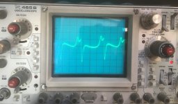
Thanks ! Would actually be good news as it might be easier to fix. See picture attached with the signal at TP1 on the A4 board. Scope is at 20mV, 0,5µsec. DC level at TP1 is 2,9V. (shows uncalibrated but was actually just very close to calibrated).
And also U3 on the A4 board has been replaced at a given point in time (before I got the unit), as it is on a socket.
Best Regards,
Dirk
Attachments
I'm not sure what to make of the TP1 waveform. They should be harmonically related to the test frequency, but at least they show low amplitude--- a good thing. But R23 waveform is huge, so there appears to be local oscillation within this stage. Both the U3C opamp and Q1 are under suspicion. Do you see any significant amplitude developed across R24? If Q1 is viable, there should be only 10's mV across R24.
Hello Steve,
Thank you very much for your help !
Have double checked the signal at TP1, don't see any other AC component in that signal. Running the internal oscillator at 1KHz (10x100). Activating the filters and going down to the -80dB range does not seem to impact the signal.
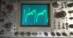
Connected my 339A through an isolation transformer to the power line and measured the signal across R24. Filters are all back off and setting is at -50dB range, showing -56dB on the meter. Connecting the scope, just either side of R24 impacts the signal, meter moves to -52dB. See picture attached with the measured signal across R24. Scope is at 0,5V and 1µsec. Quite a bit more than a few tens of milivolts and frequency is now down to about 300KHz. Of course, the 339A is not connected to ground during this measurement.
Have also measured the output of U3C. See second picture attached, scope is at 5V and 0,5µsec.
Started to look up data for Q1 :- ))
Best Regards,
Dirk
Thank you very much for your help !
Have double checked the signal at TP1, don't see any other AC component in that signal. Running the internal oscillator at 1KHz (10x100). Activating the filters and going down to the -80dB range does not seem to impact the signal.
Connected my 339A through an isolation transformer to the power line and measured the signal across R24. Filters are all back off and setting is at -50dB range, showing -56dB on the meter. Connecting the scope, just either side of R24 impacts the signal, meter moves to -52dB. See picture attached with the measured signal across R24. Scope is at 0,5V and 1µsec. Quite a bit more than a few tens of milivolts and frequency is now down to about 300KHz. Of course, the 339A is not connected to ground during this measurement.
Have also measured the output of U3C. See second picture attached, scope is at 5V and 0,5µsec.
Started to look up data for Q1 :- ))
Best Regards,
Dirk
Attachments
Hi Dirk,
I'm suspicious of Q1.
You mentioned U3 is socketed. I suggest removing the opamp and connecting a 100K resistor from Q1 base to +15V. Then measure voltages at R23 and at emitter and base of Q1. That will tell us a lot about Q1 health.
I don't think you need to resort to the isolation transformer for most testing. Do make sure to use x10 scope probes. X1 probes have large capacitance that can provoke oscillation, especially in middle of opamp circuits.
Hi Steve,
Will do the test but can take a couple of days before I come back to you, grandson was unexpectedly taken to hospital yesterday evening.
Meanwhile, again many thanks for this great help and your advice.
Dirk
Will do the test but can take a couple of days before I come back to you, grandson was unexpectedly taken to hospital yesterday evening.
Meanwhile, again many thanks for this great help and your advice.
Dirk
Grandson can hopefully return home today and continue to recover there.
Have done the above suggested test, connected a 100K resistor between 14V and the 100 Ohm resistor that is connected to the base of Q1
The resistor measured 99,2kOhm.
Best Regards,
Dirk
Have done the above suggested test, connected a 100K resistor between 14V and the 100 Ohm resistor that is connected to the base of Q1
- 15V is actually 14,73V
- base is at 8,41V. That yields a current of 0,06 mA.
- emitter is at 7,75V.
- R23 is at 6,12V. That yields a current of 17,7mA
The resistor measured 99,2kOhm.
Best Regards,
Dirk
Hi Dirk,
I home your grandson's trouble is nothing serious and that he has a speedy and complete recovery.
Your measurements suggest Q1's beta is about 300--- very healthy, at first blush. I was guessing it would be near unity and a clear culprit. I'd suggest trying a new opamp. From the added socket, I'd guess the supplied opamp was a replacement of the OEM device. What type is it? Same questions re Q1.
If the problem persists, look at +15 rail near the U3 and Q1 for any evidence of ~400KHz waveform, and scrutinize nearby 15V supply bypass capacitors (e.g. C9, C10). A desperation experiment would be to add a 0.01uF cap between U3 pins 8 and 9 (to add some local gain roll-off) and note any change in behavior.
Best regards,
Steve
Hello Steve,
Took a bit longer then expected but grandson is home since this morning. The good news is that he is fully recovered, back to school on Monday !
And the mystery is solved. You were absolutely right, is not the photomodule, it is indeed U3. Have exchanged U3 and U5 and the signal at TP1 is now perfectly stable, no 450kHz noise any more. Both U3 and U5 have the 1826-0315 marking and seem to be the correct HP parts. Q1 is never replaced, is the original component.
Plan to replace both U3 and U5. Is it best to look for the original HP 1826-0315 or would it be better to use a new LM348N ? More familiar with tube (amp) gear and not so much with opamps, can use some guidance here.
Many, many thanks for your help !
Sincerely,
Dirk
Sounds like you're enjoying good news on several fronts! 🙂
I think a new LM348N ought to be fine, and I imagine you'll pay a real premium for an H-P branded part. And from your earlier bias test on Q1, I'm thinking Q1 probably wasn't the issue.
Best,
Steve
I think a new LM348N ought to be fine, and I imagine you'll pay a real premium for an H-P branded part. And from your earlier bias test on Q1, I'm thinking Q1 probably wasn't the issue.
Best,
Steve
Hope it's OK to post here - seems to be the most recent HP339A thread...I picked one of these up the other day. I have done some of the 'Operational Verification Checks' - and everything seemed to be working ok. But I figured as old as it is I should take a look inside - for the most part looks pretty good, a few obviously leaking electrolytic's of course...and a couple of things I wanted to ask about. First is the rear board seems to be different than the front boards, and the pictures I have seen online - not the same gold traces. And the other more concerning thing was a 'smoke' residue in the power supply area - I thought that one of the big filter caps had blown, but I pulled all of them and they look ok. I will be replacing them of course, but I am at a bit of a loss as to where the smoke residue came from. It is most noticeable on the base of the big caps (and the lid of the transformer), not enough on the PCB to really get any idea where it came from...wondering if anyone has any ideas what it was? Obviously it did seem to be working, but just wanted to check on this before I place my order for parts.
I plan to replace all of the obviously leaking and easy to access capacitor's, and the output level pot - are there any other things that I need to check or change?
.JPEG")

I plan to replace all of the obviously leaking and easy to access capacitor's, and the output level pot - are there any other things that I need to check or change?
I don't recognize the residue you're observing. If you transfer residue onto a clean cotton swab, any insight? Dusty, oily, color, etc?
My standard advice is to let your repairs be driven by failed performance measurements. And try to get the analyzer working so that you can baseline its performance as received before undertaking DIY improvements--- so that you can track progress incrementally.
Good luck with your new acquisition!
My standard advice is to let your repairs be driven by failed performance measurements. And try to get the analyzer working so that you can baseline its performance as received before undertaking DIY improvements--- so that you can track progress incrementally.
Good luck with your new acquisition!

Thanks Steve. I tried to wipe it off on a clean white cloth and couldn't really make out anything...kind of looked like dust. I will try to look around in there a little more - other than the residue on the lid and caps there is only one half of one of the diodes, somewhat visible in the middle of the second picture.
I have ordered replacement caps, although they looked good and I considered putting the originals back in - I figured I already pulled them so might as well. But other than that I plan to heed your advise and just replace the 3 others caps that I can see have visible leaking for now - and then use it. I will probably have a few questions once I get it back up and running.
Cheers,
Brent
I got the replacement parts today and installed them - seems to be working ok. The one thing that I am not understanding is how to read the meter...and especially having problems with what I am seeing on the meter and reading on the scope. When I set the output of the Oscillator to, for example .1v output - I am seeing 180mV on my oscilloscope - but I can't figure out how to read that on the 339A meter!
- Home
- Design & Build
- Equipment & Tools
- Could use some help repairing my HP 339A