Thanks a lot for all the recommendations, very important indeed.
A dedicated linux PC image is easier for me to prepare than the RPi4-based "smart" USB audio device. Also cheaper - RPi4 + decent PSU + reliable SD card cost $60+.
It would mean running all the measuring software in linux. As of software there is multi-platform donationware REW in java and commercial Arta in wine.
But that implies using linux desktop for the whole measurement, making screenshots, sending files, connecting to wifi, etc. I have used linux for 20 years, but would people be OK with it? Honestly, I do not want to end up supporting ordinary desktop operations instead of supporting measurement/compensation issues. That was my main reason for the "smart USB soundcard" solution - it can be connected to any existing system.
This is exactly what I am talking about https://www.diyaudio.com/forums/pc-...e-music-server-player-os-363.html#post5954948 (daphile = gentoo linux)
If you want to reach the majority of the public, linux is not the best idea, IMHO.
RPi4 is a more popular solution.
Why would 60USD a problem, when any other solution will cost >> 1kUSD ?
A "smart USB soundcard" is IMHO a very good solution.
Just my personal view,
Patrick
RPi4 is a more popular solution.
Why would 60USD a problem, when any other solution will cost >> 1kUSD ?
A "smart USB soundcard" is IMHO a very good solution.
Just my personal view,
Patrick
What this "application" can do is very specific. I'm not sure it makes sense to pretend to be all things audio measurement. All it really needs to do is present the distortion corrected interfaces and move frequency specific audio through them and very specific levels (or it won't work).
I think you could use something like Pulse audio to run the audio apps on a windows PC but connect to a Linux PC or RPI for the actual audio interface. Latencies etc. may be issues for some software. Conceptually it would work for both a RPI and an X86 platform. The X86 does not need to be "latest" and most of the best soundcards well supported in Linux on X86. I believe most of the magic is at the ALSA level looping through Pavels algorithms.
I think you could use something like Pulse audio to run the audio apps on a windows PC but connect to a Linux PC or RPI for the actual audio interface. Latencies etc. may be issues for some software. Conceptually it would work for both a RPI and an X86 platform. The X86 does not need to be "latest" and most of the best soundcards well supported in Linux on X86. I believe most of the magic is at the ALSA level looping through Pavels algorithms.
Yes, applicability of the distortion compensation is limited to specific measurement methods. Nevertheless the needed output/input frontend is identical for all the other methods. With the soundcard/DUT already connected, it would make sense to perform all other measurements with the same setup in the pass mode (compensation off).
IMO the tool should explore more options offered by the software/hardware interaction, being part of the "smart soundcard", independently of the actual measurement software, e.g.
* Software-calibrated input/output levels
* Automated input gain (as discussed in the PMA's thread) would be quite simple (with precisely aligned balanced-input divider actuated by two inexpensive steppers)
* Scripting of automated measurements - the compensation SW already includes a generator (with any distortion added if needed) and continually runs detailed FFT on the incoming signal, even in the pass mode.
* Inverse-FFT-generated signal with all noise below some level removed (not sure of a practical use case but maybe there is some") ).
).
* Anything added later on by upgrading the firmware...
IMO the tool should explore more options offered by the software/hardware interaction, being part of the "smart soundcard", independently of the actual measurement software, e.g.
* Software-calibrated input/output levels
* Automated input gain (as discussed in the PMA's thread) would be quite simple (with precisely aligned balanced-input divider actuated by two inexpensive steppers)
* Scripting of automated measurements - the compensation SW already includes a generator (with any distortion added if needed) and continually runs detailed FFT on the incoming signal, even in the pass mode.
* Inverse-FFT-generated signal with all noise below some level removed (not sure of a practical use case but maybe there is some
).* Anything added later on by upgrading the firmware...
Precisely derived jacobian matrix for nonlinear regression instead of the default numerically calculated derivatives yields measurably more precise splitting of the DAC/ADC distortions CALIB: using custom precisely calculated jacobian (vdlpDfdp.m) instea… * pavhofman/nonlinear-compensation@eb098e7 * GitHub Now I get almost no THD difference between VD and LPF paths. I cannot see any other possible explanation but clean DAC output.
All commits pushed to the github repo.
I am working on automated calibration as the manual one is boring and prone to operator errors.
All commits pushed to the github repo.
I am working on automated calibration as the manual one is boring and prone to operator errors.
I will prepare for download a bootable linux mint image with the manually-operated compensation pre-installed. Of course it will require a manually-operated compensation adapter.
For now I cannot tell about the automated version, still lots of work ahead.
Thanks for your interest.
For now I cannot tell about the automated version, still lots of work ahead.
Thanks for your interest.
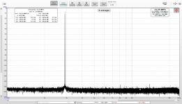
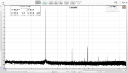
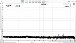
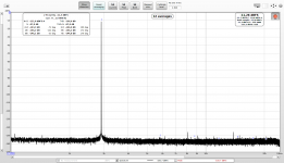
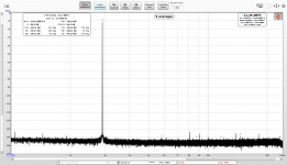
Unfortunately I have no means of precise measuring for now, but this is why I think the DAC side is clean:
1. Combined (DAC+ADC) distortions of voltage-divider path compensated on ADC side.
2. After switching to LPF, the compensation performance is gone - the LPF changes the DAC-side distortions, resulting in totally different DAC+ADC distortions than those being compensated.
3. DAC-side-only contribution compensated + the signal is passing through the voltage divider. ADC side not compensated
4. After switching to the LPF, with the DAC-side-only compensation kept running. Notice the similarity of level and phase of the harmonics on this (LPF) and the previous (VD) screenshot. Basically no change, yet radically different loopback path.
5. The remaining distortions compensated on ADC side while signal passing through the voltage divider.
6. After switching to the LPF - THD changed from -136.9dB to -134.8dB.
Attachments

Last edited:
The screenshots are from REW. The tool sits between the measurement software and the soundcard (plus the hardware calibration adapter, of course). I develop on linux where virtual sound devices are standard part of the sound subsystem. REW/Arta/Diana all run fine in linux.
Technically, the method could be built into the measurement package directly. Practically - it is quite a big piece of rather non-trivial code and the license is for open-source projects.
Currently I am working on automated calibration adapter - SW support as well as the actual adapter (hopefully PCB sent for manufacturing this week).
The first "product" stage will be the automated USB-controlled HW adapter and amd64 image of pre-configured Linux Mint, with user-supplied soundcard.
The final plan is still the fully-contained RPI-based USB audio device usable in any OS. User will plug his existing USB sound card into the RPi. The RPi4 part is coming along slow but nicely, the project has already generated a few patches in the USB audio gadget code of linux kernel, many more to follow.
Actually there are already a few un-related use-cases waiting for the generally-usable USB audio gadget code.
Last edited:
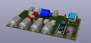
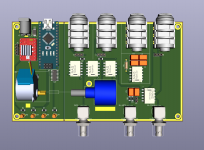
First draft of the PCB. The 3D printed enclosure will have two separately shielded sections (copper tape) - for the controller part and for the actual calibrator. The two parts are galvanically isolated (no high-voltage protection though + still need to work on larger clearances between the relay control traces and the analog ground planes). The upper part of the enclosure will further divide the calibrator into shielded sections, to separate the voltage divider from the LP filters so that phase-difference calibration is as precise as possible.
The board is ready for dual-tone generator (single-tones from separately compensated left and right channels are mixed by resistors - to be tested) and two switchable LP filters to cover larger frequency range.
Soundcard terminals: support for soundcards with single ended or balanced inputs/outputs, configurable with jumpers.
DUT terminals:
* single-ended compensated output
* balanced input (two BNCs) - hot line compensated, cold line for common-mode rejection of ground loops.
By-passable 2nd order passive filter at the hot-line input for testing impact of wideband noise on distortion.
Status LEDs:
* PWR: 12V power for the stepper
* CTRL: communication with the software is established
* OUTPUT: output terminal to DUT is active
* INPUT: input terminal from DUT is active
Attachments
Last edited:
Hi phofman,
Very interesting project!
I would like to give a try to your software. Last git commit is from november last year. Are there significant updates not commited yet?
Still on SW side, does the the interface allow the manual calibration in a didactic way?
On hardware side, I didn't get the interest of the VD. Is it only to have the ADC in it's best working range? If not, could you please explain?
At last, one method to lower the noisefloor is to sum channels. In theory, 3 dB are gained each time a channel is added.
Do you think that alsaconf would allow synchronous summing?
Hi phofman,
Very interesting project!
Thanks. The practical effect is still to be measured, but it's coming...
I would like to give a try to your software. Last git commit is from november last year. Are there significant updates not commited yet?
Most of the new commits (not pushed to the github repo yet) are related to the automated calibration. But the octave project is just one step of the overall installation. Do you have any linux experience?
Still on SW side, does the the interface allow the manual calibration in a didactic way?
The new calibration code will offer three adapter configurations:
a) manual switches and manual pot operation - the software waits for user clicking on OK button.
b) manual switches and stepper-actuated pot (for my situation now when the stepper just sits on top of the existing switch-based adapter) - the software waits for OK button for manual switches, then adjusts the pot automatically
c) automated relays and stepper-actuated pot, i.e. the worked-on PCB above - the software controls relays and the pot automatically
On hardware side, I didn't get the interest of the VD. Is it only to have the ADC in it's best working range? If not, could you please explain?
Well, the VD is key part of the process. Before calibration measurements are taken, the output VD level must be very precisely aligned with output level of the LP filter so that ADC distortion profile is virtually identical for both cases. Only then can the system be described by two equations for two complex variables, solvable by nonlinear regression.
At last, one method to lower the noisefloor is to sum channels. In theory, 3 dB are gained each time a channel is added.
Do you think that alsaconf would allow synchronous summing?
A multichannel soundcard has all channels synchronized, most soundcards (PCI as well as USB) communicate with sample frames where each frame contains one sample per each channel. The summing will occur in analog domain.
I have tested subtracting channels (A with signal - B with zeros) to eliminate DAC/USB frequency artefacts. While the elimination is quite effective, distortions of the subtracted signal proved harder to compensate, yielding worse results.
Summing is a different scenario. Actually I could try summing the 8 channels of my Xonar D2X, measuring with the EMU 0404 (after finishing the automated adapter). Thanks for the hint.
Yes, I am a Linux user since years, all my machines are dual boot. I can follow instructions with command lines but I will not pretend being able to do advance Linux stuff by myself.Most of the new commits (not pushed to the github repo yet) are related to the automated calibration. But the octave project is just one step of the overall installation. Do you have any linux experience?
This seems perfect for my tastes.The new calibration code will offer three adapter configurations:
a) manual switches and manual pot operation - the software waits for user clicking on OK button.
b) manual switches and stepper-actuated pot (for my situation now when the stepper just sits on top of the existing switch-based adapter) - the software waits for OK button for manual switches, then adjusts the pot automatically
c) automated relays and stepper-actuated pot, i.e. the worked-on PCB above - the software controls relays and the pot automatically
Thanks for all the explanations, and you welcome for the tip. In theory, with 8 channels you could lower the noise from the acquisition system from 24 dB! BTW, summing DACs should also lower their noise.Well, the VD is key part of the process. Before calibration measurements are taken, the output VD level must be very precisely aligned with output level of the LP filter so that ADC distortion profile is virtually identical for both cases. Only then can the system be described by two equations for two complex variables, solvable by nonlinear regression.
A multichannel soundcard has all channels synchronized, most soundcards (PCI as well as USB) communicate with sample frames where each frame contains one sample per each channel. The summing will occur in analog domain.
I have tested subtracting channels (A with signal - B with zeros) to eliminate DAC/USB frequency artefacts. While the elimination is quite effective, distortions of the subtracted signal proved harder to compensate, yielding worse results.
Summing is a different scenario. Actually I could try summing the 8 channels of my Xonar D2X, measuring with the EMU 0404 (after finishing the automated adapter). Thanks for the hint.
From the thread I had the feeling that your algorithm should be insensitive to sound card jitter, even with independant DAC and ADC. Did you confirm this by testing?
I am afraid noise in individual channels of a multichannel soundcard is not random with regards to other channels, some noise will originate from the common parts - PSU, DAC chip, etc. Summing the channels will attenuate the random noise and amplify the common artefacts.
The software supports unsynchronized DAC and ADC clocks - i.e. sampled ADC signal has slightly different frequency than the incoming digital stream to the DAC. Some parts of the algorithm are more CPU-intensive then and compensation-latency grows, because FFT can increase several times (i.e. taking more samples) when finding FFT length whose bin centers best onto the measured non-integer frequency.
But jitter has not been addressed by the distortion compensation and I think it never will (being basically a random process).
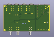
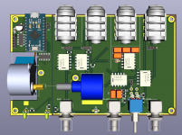
Added fully-balanced -20dB attenuator at the balanced input - it took only 4 resistors, 1 status LED, and re-arranging relays to utilize the unused halves of relays in the calibration branch (the input is never active during calibration, allowing dual-role of the calibration relays). Default (no power) operation - attenuator engaged. The attenuator will be operated by a push button in the GUI interface.
Attachments
I am using inexpensive "bourns" from ebay. They are clones of the original, but the make looks quite decent, outside and inside (from what I saw when opening one)
orig. https://uk.farnell.com/bourns/3590s-2-103l/potentiometer-10k-5-linear-2w/dp/1612611 vs. clone 10K Ohm 3590S-2-103L With 10 Turn Counting Dial Rotary Potentiometer Pot Ze | eBay
I am reasoning like this - if the pot distorted significantly, the equations would not correctly describe the circuits and the split would not work for voltage-divider and LPF paths.
It is possible the original pot would yield better results though - to be tested. The same holds for the RC filter, I will use Wima FKP2 (right now using some older axial foil cap).
The input attenuator with unused relay halves was a good placement and routing exercise last night, but fetching sensitive calibration signal and DUT output (possibly tens volts amplitude) into one tiny relay package is likely not a good idea. The two sets of relay contacts are not shielded internally.
A small angle toggle switch placed between the input BNCs may do a better job and flipping the switch is faster than clicking on a button in GUI. It will not be operated automatically at clip detection, but the detection would have a large latency anyway. A proper solution would require a dedicated relay, IMO. Maybe in next versions...
Right now I am using inexpensive silver-coated switches and the compensation seems to work OK. The gold-plated ones are quite (10x) expensive.
I should build one board with all no-compromise parts to compare the results.
Last edited:
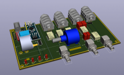
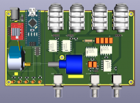
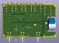
Input attenuator with simple toggle switch. LEDs are placed close to the parts they inform about:
1) CTRL - software connected
2) OUT - output BNC active
3) dual-color IN/CLIP - green - input BNC active, red - clipping on input detected, user should engage the attenuator
Using 5V geared stepper now allows powering the adapter with the USB connection only, no additional PSU needed. In addition, the inexpensive stepper is unipolar which puts less strain on power supply - no bridge fighting the induced currents is required.
The regular Arduino Nano (ATmega 328P) uses a USB-serial chip (usually CH340) which reports harcoded USB configuration parameters, including the MaxPower current. Being a simple low-consumption communication chip it requests only one unit of USB power - 100mA. Root USB ports ignore that and provide 500mA, but e.g. when plugging the adapter into a hub embedded in USB keyboard the power would not be sufficient.
It is therefore important that the adapter reports full 500mA requirement. Fortunately another Arduino variant - Leonardo - uses ATmega32u4 which features a USB receiver, configurable with the firmware. This guy reports full 500mA with its default bootloader - problem solved. At 3USD twice the price than regular Arduino, but still good deal. Plus it has a smaller footprint.
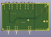
The layout is redesigned to reflect flow of the signal properly. This version (after final touches) will be sent for manufacturing.
1) CTRL - software connected
2) OUT - output BNC active
3) dual-color IN/CLIP - green - input BNC active, red - clipping on input detected, user should engage the attenuator
Using 5V geared stepper now allows powering the adapter with the USB connection only, no additional PSU needed. In addition, the inexpensive stepper is unipolar which puts less strain on power supply - no bridge fighting the induced currents is required.
The regular Arduino Nano (ATmega 328P) uses a USB-serial chip (usually CH340) which reports harcoded USB configuration parameters, including the MaxPower current. Being a simple low-consumption communication chip it requests only one unit of USB power - 100mA. Root USB ports ignore that and provide 500mA, but e.g. when plugging the adapter into a hub embedded in USB keyboard the power would not be sufficient.
It is therefore important that the adapter reports full 500mA requirement. Fortunately another Arduino variant - Leonardo - uses ATmega32u4 which features a USB receiver, configurable with the firmware. This guy reports full 500mA with its default bootloader - problem solved. At 3USD twice the price than regular Arduino, but still good deal. Plus it has a smaller footprint.
The layout is redesigned to reflect flow of the signal properly. This version (after final touches) will be sent for manufacturing.
Attachments
Last edited:
- Home
- Design & Build
- Equipment & Tools
- Digital Distortion Compensation for Measurement Setup