Op amps are just barely lukewarm.
I thought I was onto something with a chip transistor that was reading 3.5 ohms, but it turns out that transistor is not on the board layout diagram. The odd part is the resistor across it reads 3R32. The other channel has the same transistor and resistor, and it reads a couple K ohms. But the other 3R32 shows no visible damage. Maybe open resistor caused some other part to bias into saturation and take the rails down? But nothing running hot to the touch!
So far, the 20V rails to ground read about 700K ohms to the meter. So something is happening when the circuit is powered up that is acting like a crowbar/clamp only when energized. But I don't have the correct schematic and it's a multilayer PCB, which makes tracing out the circuit and drawing a schematic an untenable task.
The thought occurred that maybe the 20V regulators are unable to sustain the normal load, but appear good at no load. As far as I can tell, nothing is shorted on the analog board generator section.
I backfed power into the affected circuit and V81 went up in smoke. I re checked V82 (BD139 and instead of 3K, it now read 198 ohms from B to C. So I lifted those two pins and the 20V rails came up. But I have more transistors to replace. I hope these are not special match for low distortion.
Unfortunately, the analyzer side of the machine is still dead.
Unfortunately, the analyzer side of the machine is still dead.
UPL test programs
Fortunately my UPL is working ok. However today I tried to find out what kind of diagnostic tools / test programs are available. I found two.
selftest.bas
Not documented but results are self explaining.
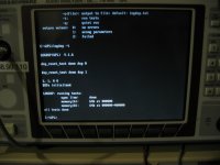
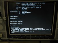
logdsp.exe
Readme file says about this one: LOGDSP.EXE: debugtool (R&S use only)
This starts from dos prompt and something can be figured out from programs short help.
I wish success with your fault finding.
Fortunately my UPL is working ok. However today I tried to find out what kind of diagnostic tools / test programs are available. I found two.
selftest.bas
Not documented but results are self explaining.
logdsp.exe
Readme file says about this one: LOGDSP.EXE: debugtool (R&S use only)
This starts from dos prompt and something can be figured out from programs short help.
I wish success with your fault finding.
Attachments


Thanks for reminding me about the BASIC diagnostic files. I had completely forgotten how to find them and run them. Had run the diagnostic when I first bought the UPL, but have since forgotten about it. This jogs my memory.
Been dealing with a plumbing emergency all day. Hopefully I can resume productive work tomorrow.
Been dealing with a plumbing emergency all day. Hopefully I can resume productive work tomorrow.
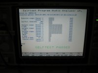
I ran the selftest.bas file today. It got as far as reporting the options installed, and did not proceed any further.
I am hoping that the Analyzer functions are inhibited because of the generator fault and that when I fix the generator section, the Analyzer will also return to operation. If not, then I have two separate failures to deal with.
I am hoping that the Analyzer functions are inhibited because of the generator fault and that when I fix the generator section, the Analyzer will also return to operation. If not, then I have two separate failures to deal with.
I also need to source a Signetics SE5534AFE op-amp. These ceramic packaged op-amps seem to be discontinued and the only sellers are in China.
Signetics was absorbed into Philips in the 1980s. The 5534 is very common. The modern versions should work fine. The ceramic is for the wider temp range but I doubt it gets that hot in that box ever.
Sent from my LG-H811 using Tapatalk
Sent from my LG-H811 using Tapatalk
I think I have some if you do want them These are pulls from upgrading Boonton 1120s.
Sent from my LG-H811 using Tapatalk
Sent from my LG-H811 using Tapatalk
As long as it doesn't affect the distortion/noise levels.
Here's what I'm about to order:
Mouser # Mfr. # Manufacturer Customer # Description RoHS Lifecycle Order Qty. Price (USD) Ext.: (USD)
726-BC850CE6327 BC 850C E6327 Infineon Bipolar Transistors - BJT NPN 30 V 100 mA RoHS Compliant End of Life 20 $0.157 $3.14
726-BC860BE6327 BC 860B E6327 Infineon Bipolar Transistors - BJT PNP Silicon AF Transistor RoHS Compliant End of Life 20 $0.157 $3.14
71-CRCW12063R32FKEA CRCW12063R32FKEA Vishay Thick Film Resistors - SMD 1/4watt 3.32ohms 1% RoHS Compliant By Exemption 50 $0.055 $2.75
652-CRT1206BY10R0ELF CRT1206-BY-10R0ELF Bourns Thin Film Resistors - SMD 1/4watts 10 ohm .1% RoHS Compliant 20 $0.307 $6.14
71-CRCW1206-56.2-E3 CRCW120656R2FKEA Vishay Thick Film Resistors - SMD 1/4watt 56.2ohms 1% RoHS Compliant By Exemption 50 $0.055 $2.75
512-BD14010STU BD14010STU Fairchild Semiconductor Bipolar Transistors - BJT PNP Si Transistor Epitaxial RoHS Compliant 10 $0.349 $3.49
512-BD13910STU BD13910STU Fairchild Semiconductor Bipolar Transistors - BJT NPN Si Transistor Epitaxial RoHS Compliant 10 $0.349 $3.49
863-SA5534NG SA5534NG ON Semiconductor Operational Amplifiers - Op Amps 3-20V Sngl Low Noise Industrial Temp RoHS Compliant 4 $1.50 $6.00
Are the opamps socketed? PM an address to me and I'll send you the ceramic ones in my collection. I would be surprised if they made a positive difference but its worth a try. I also have others.
Also add some LME49710's to the order. For the most part they are a direct drop in replacement with no connection to the terminals for offset or "enhancements" so you don't need to disconnect that stuff. DC offset is much better as is the linearity and gain/bandwidth.
I have confirmed I have 8 of the ceramic Signetics 5534's. And examples from JRC, TI and others.
I have confirmed I have 8 of the ceramic Signetics 5534's. And examples from JRC, TI and others.
Are the opamps socketed? PM an address to me and I'll send you the ceramic ones in my collection. I would be surprised if they made a positive difference but its worth a try. I also have others.
The op-amps are soldered in. Standard DIP, not SMD.
I'll PM you. Thanks!
Also add some LME49710's to the order. For the most part they are a direct drop in replacement with no connection to the terminals for offset or "enhancements" so you don't need to disconnect that stuff. DC offset is much better as is the linearity and gain/bandwidth.
I have confirmed I have 8 of the ceramic Signetics 5534's. And examples from JRC, TI and others.
PM sent. Thank you!
Got a reply from R&S this morning.. they think the analyzer is independent of the Generator. So perhaps there is another power supply rail that is out, otherwise I've got damage to the analyzer too.
I will order all of the various regulators that are used in the power supply, too, just in case.
The op-amps are soldered in. Standard DIP, not SMD.
I'll PM you. Thanks!
Mark,
I'd say there is 99% chance the Op-amps are OK, so I'd first replace everything in the output stage first.
In fact, I'm sure if you remove the 3R32 resistors in the damaged output stage section you should be able to power up OK.
Mark,
I'd say there is 99% chance the Op-amps are OK, so I'd first replace everything in the output stage first.
In fact, I'm sure if you remove the 3R32 resistors in the damaged output stage section you should be able to power up OK.
The op-amp on the channel that was used to test the bridge mono amplifier is oscillating at an RF rate. I have injected test signals via jumpers X25/24. The other channel's op amp passes signal. This damaged channel passes distorted signal with RF riding on it. I suspect that output of the op-amp saw some sort of back feed which damaged it.
I'm troubleshooting the analyzer section now, in anticipation of a parts order from Mouser. I found that I have +/-5V DC at P22/23, in the area near the 49MHz crystal. I have +/-15V DC on the two large ceramic chip caps near there.
I don't know if there are any other supply rails that are missing, but if this section gets the same power feed from the ribbon connector, then possibly the power to the entire board is okay.
The question of whether something is wrong with one of the digital boards now looms large. In spectrum analyzer mode, I should see a trace, even if no signal is input to the analyzer. I should see the noise floor on the -150dB line. But there is no trace at all. Just a grid with the X-Y labels.
The host computer UI is functional, in that I can call up various setup files, but I cannot get any sign of activity with the analyzer output to the UI.
What happens if you try a digital loopback? That should bypass all the analog stuff. You can also look for a data stream on the AES out for signs of life.
I don't have the digital option there's no SPDIF or XLR digital inputs on this particular unit.
What I have been able to determine is that all the voltages are present in the correct values on connector X3 which is the main ribbon cable from the power supply to the analog board.
What I have been able to determine is that all the voltages are present in the correct values on connector X3 which is the main ribbon cable from the power supply to the analog board.
The analyzer does this peculiar thing to where it looks like it's stuck in the loop take a look at this video clip of the upper right hand corner of the screen. Sorry about it being upside down the UPL is on the bench upside down to access the analog analog bored.
https://youtu.be/6IYPpgjYKTA
https://youtu.be/6IYPpgjYKTA
- Home
- Design & Build
- Equipment & Tools
- LCD Backlight for Rohde & Schwarz UPL?