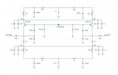
Just measured the filter, it attenuates 2 kHz 22 dB and 3 kHz 31 dB.
Inductors 3,1 mH /2,0 ohms, C´s 8,2 uF, resistors 124 ohms.
Inductors 3,1 mH /2,0 ohms, C´s 8,2 uF, resistors 124 ohms.
Last edited:
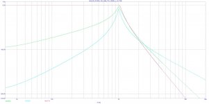
3 oscillator post filters, each with 4 or 2 + 2 inductors, so cw/ccw connection is possible.
The low pass is the steepest but has all different inductor values and inductors are in the direct signal path. Also hum goes through.
The low and band pass combination filters hum but still mostly different inductor values, 2 of them in the signal path.
The band pass has only resistors in the direct signal path, inductors all have the same value, the filter can be scaled by adding or omitting R-LC segments, it filters hum, is steep enough.
I guess this is still thee best.
Attachments
3 oscillator post filters, each with 4 or 2 + 2 inductors, so cw/ccw connection is possible.
The low pass is the steepest but has all different inductor values and inductors are in the direct signal path. Also hum goes through.
The low and band pass combination filters hum but still mostly different inductor values, 2 of them in the signal path.
The band pass has only resistors in the direct signal path, inductors all have the same value, the filter can be scaled by adding or omitting R-LC segments, it filters hum, is steep enough.
I guess this is still thee best.
What is the input impedance as a function of frequency for these three filters? The existing reference for low distortion seems to be Victor's oscillator. It has an approximate output impedance of 200 ohms. Also, the distortion of that oscillator and many others begins to degrade for load resistance in the 1k ohm to 10k ohm region. Finally, if these filters require a precision source impedance, that would interfere with their use with different oscillators unless an active buffer amplifier is put in front.
Cheers,
Bob
"...Victor's oscillator. It has an approximate output impedance of 200 ohms."
Latest boards (OPA1656 in Wien bridge) have output impedance 100 ohm - two 200 ohms in parallel.
Vic.
Latest boards (OPA1656 in Wien bridge) have output impedance 100 ohm - two 200 ohms in parallel.
Vic.
Tried REW with a few old soundcards, the best so far M-Audio 24/96
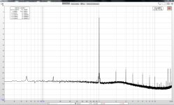
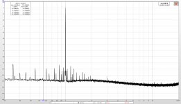
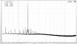
My analyzer´s output without and with the simple 2-inductor filter.
The unshielded filter picks up a lot of hum but the area of interest stays clean and
the filter clearly adds a zero to the THD number.
Input adjusted to equal levels.
My analyzer´s output without and with the simple 2-inductor filter.
The unshielded filter picks up a lot of hum but the area of interest stays clean and
the filter clearly adds a zero to the THD number.
Input adjusted to equal levels.
Attachments
Last edited:
"...Victor's oscillator. It has an approximate output impedance of 200 ohms."
Latest boards (OPA1656 in Wien bridge) have output impedance 100 ohm - two 200 ohms in parallel.
Vic.
Very good. A 50 ohm quad would be perfect.
What is the input impedance as a function of frequency for these three filters? The existing reference for low distortion seems to be Victor's oscillator. It has an approximate output impedance of 200 ohms. Also, the distortion of that oscillator and many others begins to degrade for load resistance in the 1k ohm to 10k ohm region. Finally, if these filters require a precision source impedance, that would interfere with their use with different oscillators unless an active buffer amplifier is put in front.
Cheers,
Bob
The bandpass can have any impedance, just higher impedance means higher loss. But as I want to measure power amplifiers, the gain will compensate for it.
If oscillator performance degrades a bit or it is necessary to add a uld buffer, I think it is no problem, afterwards the post filter will reduce harmonics by tens of dBs.
I am amazed by the performance of this oscillator. I want to test it myself and I already sent a message to Victor. I case i am lucky i will grab a board.🙂
I am amazed by the performance of this oscillator. I want to test it myself and I already sent a message to Victor. I case i am lucky i will grab a board.🙂
Seems to be the MOAO
"...Victor's oscillator. It has an approximate output impedance of 200 ohms."
Latest boards (OPA1656 in Wien bridge) have output impedance 100 ohm - two 200 ohms in parallel.
Vic.
Did you try balanced ?
Maybe recombining cancels some of the remaining distortion or noise.
I built a balanced DAC clock long time ago
Attachments
If you meant the balanced output of the serial 1kHz board like this (schematic of the old version):Did you try balanced ?
Maybe recombining cancels some of the remaining distortion or noise.
https://content32-foto.inbox.lv/albu...ed/1kHzBal.jpg
Then no noise cancellation. Noise is little higher and also may distort little more (some dB).
Vic.
Why did you use -5.2V, instead of -5V ?
Patrick
It is on the same supply like differential ECL comparators.
If you meant the balanced output of the serial 1kHz board like this (schematic of the old version):
https://content32-foto.inbox.lv/albu...ed/1kHzBal.jpg
Then no noise cancellation. Noise is little higher and also may distort little more (some dB).
Vic.
The picture is empty ?
I mean like in my attached schematic.
You have 1 gain device ?
2 gain devices back to back with the "tank" in the middle.
Maybe not possible.
Sorry, this link:
https://content32-foto.inbox.lv/albums/e/elterra/Balanced/1kHzBal.jpg
Balanced output drawn in red.
Vic.
https://content32-foto.inbox.lv/albums/e/elterra/Balanced/1kHzBal.jpg
Balanced output drawn in red.
Vic.
Thanks, now works.
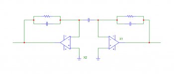
I don´t know much about oscillators and my schematic is no oscillator, just to demonstrate...
2 opamps coupled together, oscillating out of phase.
Symmetrical circuit like my crystal oscillator.
Maybe not possible because 2 feedback networks are necessary and values in feedback path can not be 100% matched.
Attachments
small news
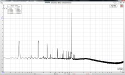
Now I made a 3.1 mH inductor, wound on a HQ audio transformer core incl. MU shielding.
With the coil inserted in the signal path after my 16 bit generator / simple bandpass filter, the distortion is equal to "no coil". See two screenshots.
However... Measured with my handheld Multimeter the coil Rs is near zero but with my RLC meter it is 10 ohms
I don´t understand. 1 layer with 0.8mm wire, about 20 windings.
If I put that inductor in my filter will it behave like a 10 ohms coil ???
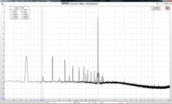
Attachments
Last edited:
- Home
- Design & Build
- Equipment & Tools
- Low-distortion Audio-range Oscillator