Finished soldering and started to power up my Shiga.
PSU (moddified to higher end version according to threads in this title... Panasonic FC, Elna, Silver Mica and so on). Result --> Very smooth 7.99 to 8.01V. Ok.
Wired up my Shiga Board. Result:
- Laser transport motor brings the laser to the CD spindle motor. I assume this should be this way.
- Backlight is nice and shiny
- LCD is powered up and working.
Problem:
- Shiga does not react on pressing the "CD Door" Button and as such, does not start the CD spindle motor. The LCD keeps showing " - - ". I checked the voltage on J3 connector. According to the schematic, there should be 5V on Pin 3, which are existing.
Any ideas on a solution?
Regards,
Fabian
Fabian,
With a camera check if the laser is on durring TOC reading.
Also check carefully if LA9242 have all pin soldered properly and there is no shortcut between adjacent pins. Same for LC78601.
A cracked ceramic capacitor can be also an issue.
As long there is everything properly soldered, the kit will work from the very first start.
Regards,
Tibi
Finished soldering and started to power up my Shiga.
PSU (moddified to higher end version according to threads in this title... Panasonic FC, Elna, Silver Mica and so on). Result --> Very smooth 7.99 to 8.01V. Ok.
Wired up my Shiga Board. Result:
- Laser transport motor brings the laser to the CD spindle motor. I assume this should be this way.
- Backlight is nice and shiny
- LCD is powered up and working.
Problem:
- Shiga does not react on pressing the "CD Door" Button and as such, does not start the CD spindle motor. The LCD keeps showing " - - ". I checked the voltage on J3 connector. According to the schematic, there should be 5V on Pin 3, which are existing.
Any ideas on a solution?
Regards,
Fabian
Have you check this...
Attachments
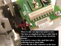
@BMW, thanks for helping, but solder blob was removed before.
Checked the laser. As far as I know, I should see a red beam through my mobile phone camera. There is none.
If I bridge Pin 2 & 3 on J2, the CD motor spins up, laser transport moves to the right with the lens adjusting trying to read something. Of course, as the laser is not working, it doesn't find any tracks and starts to show " 00 " on the display. After some time shorting, spinning motor stops and laser transport stays at the outer side of the CD. After pressing the CD Door button, the transport moves back to the inner side.
But first things first... how to start solving the laser problem?
Regards,
Fabian
Laser Intensity
Hi Tibi,
I want to join in at this point in the laser discussion. My Mk11 works fine but it only works with new CDs that have zero scratches and surface contamination. My old 1986 philips player wipes the floor in comparison and plays all my CDs from the oldest to newest. I was expecting a similar or better performance with the shigaclone based on what others have posted here.
I've checked all the connections and the ribbon cable etc. I even substituted a new drive that you supplied me additional to the one in the kit and get the same result. This make me question if the laser is getting enough juice. I don't see a bright light when I view the laser through a camera. Just little red stripes. This would suggest insufficient current flow. I'm not going to be home now until december which is annoying as I would like to finish this project off.
Can you post a photo of your laser viewed through the lens of a digital camera or phone camera please or maybe someone else on here can oblige us. Just want to compare what I see with other project builders.
The important capacitor C8 that affects the tracking is a 0.1uF MK1837 on my board.
Cheers
Aleks
Aleks,
You have first Shiga or MKII one ?
MKII is able to reaf thye most scrached CD's. I even posted a movie with Shiga MKII reading perfectly a CD with 9 radial deep scratches.
Some of the first version had suffered by the problem mentioned by you, but these have been addressed in MKII.
Measuring an infrared with a camera is irrelevant because each camera type have different sensors CCD, CMOS etc. The intensity of infrared seen on camera is related to this sensor. For example, on my Jolla phone I barely see something when I put the camera above laser, while with my old Nokia N8 this is bright and I clearly see laser operation.
Regards,
Tibi
Last edited by a moderator:
Aleks,
Can you please detail your problem ?
When you say "only work" what are the simptoms ?
Does not read TOC and fail to play CD, or have skips or loose tracking at any scratch ?
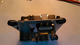
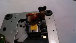
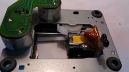
I see that the kit is mounted by you. Can you post some high resolution macro pictures ?
Have you looked for any cracked ceramic cap ?
Regards,
Tibi
Can you please detail your problem ?
When you say "only work" what are the simptoms ?
Does not read TOC and fail to play CD, or have skips or loose tracking at any scratch ?
I see that the kit is mounted by you. Can you post some high resolution macro pictures ?
Have you looked for any cracked ceramic cap ?
Regards,
Tibi
Last edited by a moderator:
Hi Tibi,
TOC is ultra quick and read first time. The issue is that it won't play scratched or even discs with very light surface marks or surface contamination. It just sits there stuck when it gets to a scratch or other artifact. I've been over the board with a microscope and can't find any issues and I have many years experience soldering surface mount components. Brand new discs play fine.
If Q1 was damaged in any way would this have an affect. I noticed that the website shows that the minikit should have a 2sa608NF but was supplied with 2N4403. I'm aware of the difference in the pinout.
I can't do much until I get home in december but want to plan my attack in advance. Guess i'll measure what is happening around Q1 initially and maybe replace this part with 2sa608nf. As i said i wasn't happy with what I was seeing through my camera. I use the camera for the same purpose testing infrared transmitters as part of my day job and usually I see a big whitish area on the screen of my phone camera. I'll take some readings when I'm home of circuit conditions and get back to you.
Thanks
Aleks
Has anyone tried using silver epoxy on the XLR5 mods especially on the copper ribbon cable on the older version transport mech. It sounds like a feasible idea if it works as soldering on the ribbon would be taken out of the equation , it is a very small space to work in with a soldering iron if you have ever seen one. Thanks!!
Steve
Steve
Has anyone tried using silver epoxy on the XLR5 mods especially on the copper ribbon cable on the older version transport mech. It sounds like a feasible idea if it works as soldering on the ribbon would be taken out of the equation , it is a very small space to work in with a soldering iron if you have ever seen one. Thanks!!
Steve
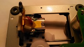
Actually, soldering on that ribbon cable ,with a proper soldering iron, it is quite easy.
At least Dimitrios and me managed to do that.
Regards,
Tibi
Attachments
Any idea what temperature you working at to remove ? I have found 2 of these versions to work on. I have just about rounded up my BoM to start building on this project, I just have to do transformer and CD puck out of the current GB. I know there are pictures posted but is there a text of the locations for the high end board mods, I see parts listed but not specific locations for them, I have tried going through entire postings and I may just be missing it. I plan on doing the 2 additional power supplies also.Thanks again! PS. I do use a good soldering/rework station.
10n on C8 is not stable. I haven't installed tent osc or external pwr yet. It loses its track but keeps on rotating... Sound mutes but mostly there is tiny periods when it finds the track again and loses it a few seconds later. 100n worked perfectly.
How is a smaller value on C8 affecting sound? Supposedly faster tracking? In that case mine becomes to fast") I´ll try 47 and 82 nF before I return to 100nF which worked flawlessly.
I´ll try 47 and 82 nF before I return to 100nF which worked flawlessly.
Regards
How is a smaller value on C8 affecting sound? Supposedly faster tracking? In that case mine becomes to fast
I´ll try 47 and 82 nF before I return to 100nF which worked flawlessly.Regards
Last edited:
- Home
- Source & Line
- Digital Source
- Shigaclone MKII Black - The builders Thread