Hi Mooly,
Who ... me?") Yeah, a couple of times.
Yeah, a couple of times.
Yes, an oscilloscope is absolutely a required basic instrument. Normally you need to go to a 20 MHz analog scope in order to get the 0.5 uS / div timebase needed to view an eye pattern. The frequency isn't that high, but keep in mind that the vertical amplifier may be -3 dB at 20 MHz, so what voltage error will there be at the RF pattern frequencies? For a DSO, the industry accepted multiplication factor for sampling rate vs signal frequency is 5:1. So to look at a 10 MHz waveform, you need a 50 MHz DSO to properly view it. That means a 100 MHz analog scope should be replaced by a 500 MHz DSO.
Various digital volt meters react differently to AC signals riding on a DC voltage. Many less expensive models simply peak detect everything an report that as the DC voltage. Hmmm, it just lied to you. That's one reason why an oscilloscope is so important. The better digital voltmeters (Fluke, HP/Agilent/Keysight) can RMS detect the AC and the DC individually and report one or the other, or add them which gives you the true effective DC voltage (heating power) of the voltage you are looking at. Some even have dual displays to report the AC signal individually. The right meter can save you from making massive mistakes.
Anyway, I'll return you to Mooly's excellent thread on restoring a CD player.
-Chris
Who ... me?
Yeah, a couple of times.Yes, an oscilloscope is absolutely a required basic instrument. Normally you need to go to a 20 MHz analog scope in order to get the 0.5 uS / div timebase needed to view an eye pattern. The frequency isn't that high, but keep in mind that the vertical amplifier may be -3 dB at 20 MHz, so what voltage error will there be at the RF pattern frequencies? For a DSO, the industry accepted multiplication factor for sampling rate vs signal frequency is 5:1. So to look at a 10 MHz waveform, you need a 50 MHz DSO to properly view it. That means a 100 MHz analog scope should be replaced by a 500 MHz DSO.
Various digital volt meters react differently to AC signals riding on a DC voltage. Many less expensive models simply peak detect everything an report that as the DC voltage. Hmmm, it just lied to you. That's one reason why an oscilloscope is so important. The better digital voltmeters (Fluke, HP/Agilent/Keysight) can RMS detect the AC and the DC individually and report one or the other, or add them which gives you the true effective DC voltage (heating power) of the voltage you are looking at. Some even have dual displays to report the AC signal individually. The right meter can save you from making massive mistakes.
Anyway, I'll return you to Mooly's excellent thread on restoring a CD player.
-Chris
I'm hoping one of the experienced techs on here might be able to help me with the laser adjustments on my Sony 333ESD (BU1-E laser) which came to me non-working terrible state and which I've been trying to restore.
After cleaning the laser optics, cleaning and lubricating the transport mechanism and having a go at the tracking gain and focus gain adjustments I've now got the player to the stage where it will play some discs OK but still skips with others. Last night it played four full albums back to back without a hiccup but then failed on the fifth disc. It feels like I'm tantalising close to getting this wonderful machine working again!!
I just bought my first oscilloscope for this but I'm still very much a novice at using it. I've also got a copy of the service manual which gives instructions on setting the focus and tracking gain and something called RF PLL but it doesn't give any instructions for setting the EF bias/balance.
What I'd could really do with is some clear instructions on where to connect the probes and which trimpot to turn for setting the EF balance.
The manual is downloadable here: Sony CDP-333ES Manual - Compact Disc Player - HiFi Engine
Last edited:
The PLL (phase locked loop) requires a frequency counter, however there is absolutely no reason to suspect there is a problem with that unless its been altered in the past.
(HiFi engine isn't listing any manuals for this model at the moment)
Sorry Mooly, I thought I'd got the download from there, my mistake. Try this link instead:
Sony CDP-333ESD CDP-605ESD Service Manual PDF Free Download
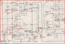
So this player uses the BU 1 pickup/pcb. You need to look at the RF on the scope at TP101 for a start. Use a low capacitance divider probe so as not to affect the signal.
The control with a cross through it is laser power so do not alter this. The focus bias should be adjusted to give the best recovered waveform at TP101 (highest amplitude, best defined diamond structure). The setting up is realy the same as I outlined in this thread for the KSS240 but don't be under any illusions... this isn't a user friendly player to work on as a first attempt.
The control with a cross through it is laser power so do not alter this. The focus bias should be adjusted to give the best recovered waveform at TP101 (highest amplitude, best defined diamond structure). The setting up is realy the same as I outlined in this thread for the KSS240 but don't be under any illusions... this isn't a user friendly player to work on as a first attempt.
Attachments
Thanks Mooly, I really appreciate your help with this!
This first photo shows what I get with the probe connected to TP101 and with the ground/earth of the probe connected to digital ground at TP 102. Apologies for the poor photo.
These are the specs of the only probe which I own at present:
This first photo shows what I get with the probe connected to TP101 and with the ground/earth of the probe connected to digital ground at TP 102. Apologies for the poor photo.
An externally hosted image should be here but it was not working when we last tested it.
These are the specs of the only probe which I own at present:
An externally hosted image should be here but it was not working when we last tested it.
Hang on, you can disregard that last post. I didn't have the scope set-up correctly.
This is the correct photo:
This is the correct photo:
An externally hosted image should be here but it was not working when we last tested it.
Last edited:
And here's an even better attempt. The trace looks sharper and less blurred in real life, the camera makes it look worse.
An externally hosted image should be here but it was not working when we last tested it.
That looks basically OK. I haven't got the manual on this PC but normally the RF level would be around 1.2 volts pk/pk or so. I'm assuming your scope is on 0.05v/div in the picture (the probe spec is fine).
The preset RV101 I circled should alter the amplitude and definition of what you see. Its a straightforward adjustment, the optimal point being the biggest and clearest pattern. If its already at that point then altering it it will only make the signal worse so you will only know by trying.
The preset RV101 I circled should alter the amplitude and definition of what you see. Its a straightforward adjustment, the optimal point being the biggest and clearest pattern. If its already at that point then altering it it will only make the signal worse so you will only know by trying.
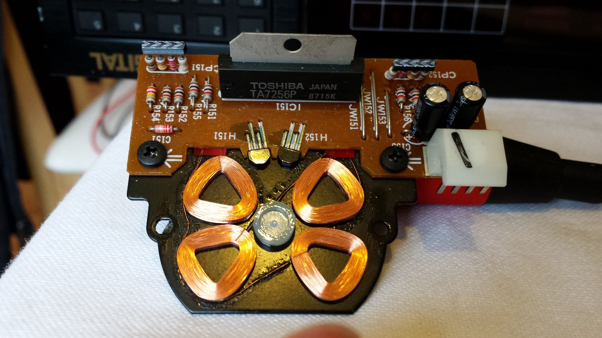
That doesn't sound good tbh. The amplitude should peak and then fall away as the pot is turned further. I wonder whether there is a problem internally with the photo-diode array within the pickup. A typical failure mode is for them to go leaky internally which upsets the biasing. Short of replacing the pickup there is no fix for that.
anatech had some thoughts on this... and that is that the platter height could be incorrect.
So it might be worth looking at the platter motor and platter. The BU 1 chassis/pickup isn't a player I'm familiar with but I think it uses a 'brushless' motor. Going off some players I have worked on there might be a nylon end float adjustment screw on the motor base. The platter shaft rests on this and so it sets the height of the platter. You would have to examine motor to see if it has this. If the player has had zillions of hours use then there could be wear on the adjuster and the platter shaft has dropped slightly as it wears its way into the screw. We are talking 10th's of a millimetre here.
The other thing that could have happened is simply that the platter has moved down the shaft. Knowing Sony, it could well be secured by one or two small Allen type locking screw. You would need to make a judgement call on whether it might have moved.
So something to look at but be very very careful. What worries me is that the player already seemed to be set at the optimum point for focus but that setting is 'one ended'. That suggests either the setting was factory set at that point or the player might have some hidden history.
Once you start adjusting mechanical and electrical adjustments together then its easy to totally screw up the player.
Another point... if the player was in as a bad a state as you mentioned earlier (and particularly if its been in a smoky environment) then there can be contamination of the internal optics within the pickup.
Thanks again for the excellent suggestions Mooly and thank you Anatech for contributing.
I've had a rather fruitless morning working on the 333ESD. Here's an update:
This player does indeed have a brushless motor. I started by removing the baseplate to see if there was a screw to adjust the spindle height. Unfortunately there wasn't, the bottom of the spindle rests in a nylon cup and apart from replacing the cup there is no way to accommodate for wear at this end.
I cleaned out the old lubricant with a Q-tip and gave it tiny blob of fresh synthetic grease.
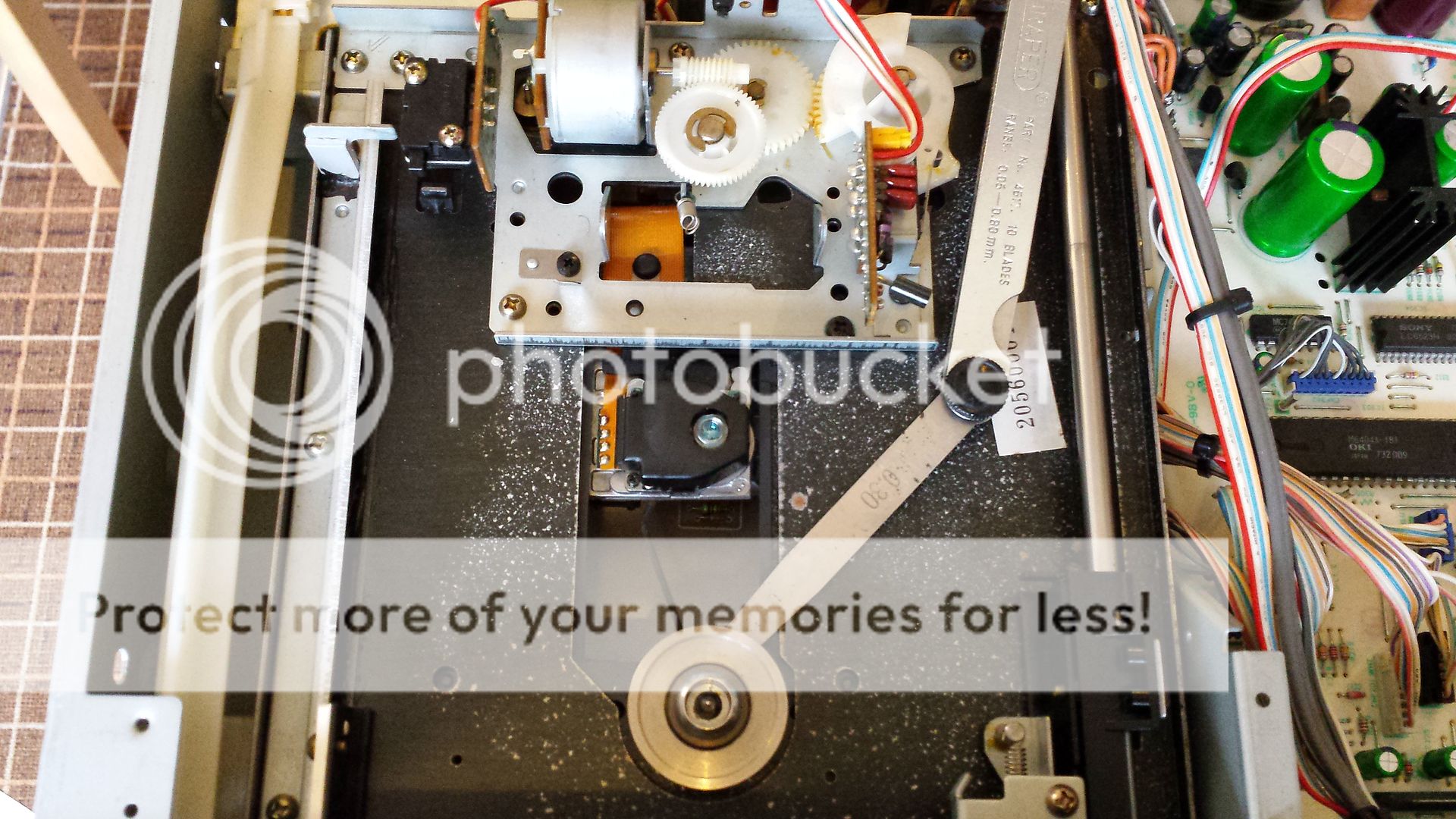
At the top of the spindle is a metal platter which is fixed to the spindle with a small hex-key grub screw. Aha...so that's how to adjust the height then.
I measured the distance from the base of the platter to the transport base plate/chassis with feeler gauges and made it out to be 0.25mm. I then loosened the grub screw and using feeler gauges reset the height to 0.30mm.
In this photo you can just about make out the small allen key.
Unfortunately my efforts seem to have been in vain. After raising the platter by 0.05mm the max RF waveform was still achieved with the trimpot on the max setting and was still only 1v pk/pk.
Overall the player just didn't seem as happy with the new platter height so I then reversed my adjustment and have put the platter back to where it was at 0.25mm.
Finally, while I was at it the top bearing of the spindle was given a drop of synthetic oil carefully chosen for use with sintered bronze bearings.
I might not have fixed the player yet but I'm learning a lot here though so it's all good
Looking at the schematic can you advise me where to connect the probe so that I can have a go at setting the EF balance?
I've had a rather fruitless morning working on the 333ESD. Here's an update:
This player does indeed have a brushless motor. I started by removing the baseplate to see if there was a screw to adjust the spindle height. Unfortunately there wasn't, the bottom of the spindle rests in a nylon cup and apart from replacing the cup there is no way to accommodate for wear at this end.

I cleaned out the old lubricant with a Q-tip and gave it tiny blob of fresh synthetic grease.
At the top of the spindle is a metal platter which is fixed to the spindle with a small hex-key grub screw. Aha...so that's how to adjust the height then.
I measured the distance from the base of the platter to the transport base plate/chassis with feeler gauges and made it out to be 0.25mm. I then loosened the grub screw and using feeler gauges reset the height to 0.30mm.
In this photo you can just about make out the small allen key.

Unfortunately my efforts seem to have been in vain. After raising the platter by 0.05mm the max RF waveform was still achieved with the trimpot on the max setting and was still only 1v pk/pk.
Overall the player just didn't seem as happy with the new platter height so I then reversed my adjustment and have put the platter back to where it was at 0.25mm.
Finally, while I was at it the top bearing of the spindle was given a drop of synthetic oil carefully chosen for use with sintered bronze bearings.
I might not have fixed the player yet but I'm learning a lot here though so it's all good
Looking at the schematic can you advise me where to connect the probe so that I can have a go at setting the EF balance?
For EF balance you need to monitor the tracking error voltage (TE) which you can pick up on the 'top' of tracking gain preset. Turn the scope timebase to a slowish speed and then jump tracks, say track 1 to the end track and then back again. During the time the pickup is moving, the waveform should look symetrical above and below ground. Its an easy adjustment, if you misalign it each way as a test, then you know what to aim for.
With regard to the spindle height... I'm puzzled that the focus bias is getting toward 'optimal' with the preset at one end. That I'm afraid is not normal.
With regard to the spindle height... I'm puzzled that the focus bias is getting toward 'optimal' with the preset at one end. That I'm afraid is not normal.
OK thanks, so I check EF balance at the same test point 'TE' as for tracking gain but which trimpot do I adjust? RV102? (sorry if that's a dim question).
As for the spindle height, I might have another go at adjusting it. It's very awkward to adjust without dissembling the whole mech much further which I was trying to avoid. It's possible my measurements this morning were flawed.
If the root cause of all this is likely to be smoke residue on the internal optics of the pick-up (quite possible given the filthy state it came to me in!). Then the only thing I can think to do as a last ditch attempt would be to squirt a whole load of IPA into the laser head using an aerosol and a long straw. Either that or dunk the laser head in a bath of IPA in an ultrasonic cleaner.
As it currently stands it will play some CD's perfectly without skipping but won't play others at all. It seems to like EMI and Parlophone recordings the best.
Yes, RV102.
Many many years ago I actually did what you suggest and 'cleaned' a pickup in iso. It got a non working player about 60% operational. Maybe an ultrasonic bath is better but these are all final options, there is a good chance of making the player totally non operational doing this. If the player has signs of smoke 'damage' which is a sticky coating that gets on everything and doesn't just dry wipe off then its a fair bet that the optics are covered in that too. Its not just the lens you can see (and its underside) but the prisms and diffraction grating internal to the pickup that suffer. And the glass surface of the laser diode of course. Smoke particles get everywhere.
Many many years ago I actually did what you suggest and 'cleaned' a pickup in iso. It got a non working player about 60% operational. Maybe an ultrasonic bath is better but these are all final options, there is a good chance of making the player totally non operational doing this. If the player has signs of smoke 'damage' which is a sticky coating that gets on everything and doesn't just dry wipe off then its a fair bet that the optics are covered in that too. Its not just the lens you can see (and its underside) but the prisms and diffraction grating internal to the pickup that suffer. And the glass surface of the laser diode of course. Smoke particles get everywhere.
Hi Tony, Mooly,
The table is for sure low. That it wasn't happy corrected means it was adjusted to the new height. I haven't read the entire thread, so I might be asking the obvious and you've already been there. Have you cleaned the slide rails and applied a minimal amount of extremely light lubricant? Your bearing oil should do okay there as long as it is pure oil and nothing else. Smoke will really gum up the works.
Your eye pattern is within a good range. Don't become focused on that issue. The focus might be a little off, but it is good enough at the moment. You can go back to it. Question, looking at the right hand side of the RF pattern, is it stable or does it seem to move back and forth? Also, if you look at the tracking and focus error test points, is there a low frequency component to either? The correct amount of gain is just past the point where the low frequency hits a minimum point, but before you get a lot of high frequency content. There wil be an increasing "hiss" sound as you adjust past the correct point and increase the gain further. Reduce the gain until the hiss diminishes and the wave form on the scope becomes clear. To test this, lightly bump the CD player in play mode. With the gains set too low it will skip easily. One thing that also affects this is the suspension rubber mounts between the CD Mechanism and the player chassis. Some get rock hard over time. If this has happened, your machine will be sensitive to shocks. The only fix is to replace the mounts or figure out another way to do this. Also, don't bother with the bump test if those suspension bits are defective. The balance between low frequency and high frequency noise takes the primary test position, ignore the bump test for gain adjustments in this case.
Cleaning the laser head in an ultrasonic bath can be risky, but if there is heavy smoke contamination, you might want to try it. Make certain your medium will evaporate completely, and that it will not affect the lock bond on & in the head.
Check the bearing on that disc motor for lateral play! Also, you can check the head height on other machines that use the KSS-240a head. This setting will be a constant across all machines, so take an average from the tray loading types. Don't even measure the manual top load types as they are more likely to have low disc tables. Try to measure between the top of the head to the top of the surface that supports the CD. Mechanism to the top reference, and chassis to the top reference point can be thrown out by various other tolerances. We know for certain that the top reference to the normal position of the objective lens is the constant. The top of the head housing is the next best thing.
I'll be quiet now since Mooly is giving good advice.
-Chris
OK here's my final update for today:
Slide rails - Yes these are indeed clean and lightly lubed with a thin oil.
Lens(es) - This afternoon I managed to very carefully remove the top moving lens and cleaned both the underside of the top lens and also the top of lower lens.
Suspension - The BU1-E uses metal springs so there are no rubber parts which could have degraded.
RF eye pattern - This is at max amplitude with the trimpot at one extreme setting. The eye pattern is good with a clear diamond shape. Max achievable amplitude is just over 1v pk/pk but no more than 1.1v. I'm afraid I didn't really understand the question about movement on the eye pattern but I'll try to post a video later. I'd say it wobbles up and down slightly.
EF balance - I think I've got this set OK.
Tracking gain - I'm backing this off until the wave pattern changes or 'collapses' and then increasing it again slightly until it is stable. Does that sound OK?
Focus gain - Same as for focus gain. With a disc which the player 'likes' playing the player can be knocked quite hard without skipping.
Spindle height - This evening I increased the spindle height in 0.1mm increments from 0.25mm. After each increase in spindle height I checked to see if the RF eye pattern would reach a peak amplitude away from the extreme of the trimpot adjustment. It didn't and no matter how much I increased the spindle height the max RF I could get remained at just over 1v with the trimpot at the max setting. At 0.8mm the player stopped spinning the disc to read the TOC so I dropped it back down to more or less where I started at 0.3mm.
I don't know how significant this but with some discs it's as good as gold and yet others it skips like mad. It's as if some discs have a reflectivity which suits it but others don't and I'm talking all major title factory CD's here not CDR's.
Hopefully this link to a video of the RF eye pattern will work:
http://vid983.photobucket.com/albums/ae313/mikepickwell/20151027_1613081_zpsc5oyxugb.mp4
http://vid983.photobucket.com/albums/ae313/mikepickwell/20151027_1613081_zpsc5oyxugb.mp4
Well I've seen far far worse. The amplitude looks better to, assuming a calibrated display set to 0.05v/div.
Is the bouncing worse at tracks toward the disc end ( the edge) ? That can be caused by 'run out' of the platter, or some contamination on the platter causing the disc not to sit properly. If you look at the disc edge on then it should run 100% true with no detectable up and down movement at the disc edge. You can spin it slowly by hand to check that.
When this player jumps and skips, is it random or is it always in the same general area of travel for the sled ?
- Home
- Source & Line
- Digital Source
- Sony CDP790 and KSS240 Restoration Project