My next step would be to at the RF when it spins up and see where the amplitude is at. It will probably look blurry because of no tracking lock but the overall amplitude would be a good guide.
Hi Andrea,
Once someone starts doing random things in an attempt to do something they don't have the resources to do, you can only make things worse.
I've had enough service experience, and experience seeing what other technicians have done when they are over their head, I know this will not end well should you continue right now. There is zero reason you need to have this fixed right at this moment except that you want to fix it right now. I understand, but you can't continue just yet.
You haven't listened to me. I said early on you need to get the correct table height. You have been told it is a critical adjustment. You did move it, you have not measured another in order to set it correctly. Therefore step #1 is to put the darned table back exactly where it needs to be. We already know this isn't correct yet. So why on earth would you continue knowing this has to be set correctly first?
The next step is to observe the eye pattern - after you have the correct height. If the focus is off, the eye pattern will not be at full height, we know this.
I am trying to help you, but I am not going to waste my time when you are not following basic steps. I'll wish you luck with this.
Hi anatech,
I'm sorry I made you angry. But I haven't other machines with the same laser, so I cannot make any measure of height and therefore I cannot get the correct height. Also searching on e web. This is the reason that I didn't listen to you :-( The other way is wait, searching on the web, maybe to find that data. Or throw my machine in the bin :-( :-(
So, I don't do anything until I have a scope.
And thank you for all the time you're spending.
Last edited:
Hi Andrea,
You didn't make me angry at all. But I recognise where this will go if we don't follow the basic steps one by one. It's just that trying to help someone is a total waste of time if they won't do the required things in order.
I have been looking for a machine I can measure to get the height. In service, we don't do it that way (we use jigs). Anyway, if I can find it I will let you know. Anyone with the same transport can measure this for us as well. So the KSS-240A and KSS-210A/150A head transports are the exact same distance. Probably the KSS-213A also, but I can't be sure.
So let's just put it out there. Anyone with these heads in a CD player, can you measure between the top of the turntable to the chassis where the motor is screwed to in mm? If a few can measure this we can get an accurate idea instead of depending on one person who may get their caliper on an angle.
You absolutely need this first before you do anything. Once we have this done we can get somewhere.
As I always say. It isn't usually the big things that will get you when you aren't trained. It's the seemingly small things.
Hi Andrea,
I'm a working tech, I don't have time to play with pictures. But I have told you more than once.
From the top of the turntable to the top of the metal plate supporting the disc (spindle) motor. Simple.
I'm a working tech, I don't have time to play with pictures. But I have told you more than once.
From the top of the turntable to the top of the metal plate supporting the disc (spindle) motor. Simple.
Hi Andrea,
One hasn't come in yet. Once aI have a transport apart I'll measure it. One thing is that those Sony heads probably have a common focal distance so they don't have to redo the transport mech every time.
One hasn't come in yet. Once aI have a transport apart I'll measure it. One thing is that those Sony heads probably have a common focal distance so they don't have to redo the transport mech every time.
This was also my procedure when the disc motor (spindle motor) was replaced beforehand.Find another CD player with a KSS-240A, KSS-150A or KSS-210A head in it. Carefully measure the distance between the top of the disc table and top surface of the CDM. Use calipers or something accurate. Set yours to the same exact distance.
That is your starting point. Don't do anything else until you have it set correctly, and I mean nothing!!!
To find the right position of the motor pulley for the exact height, I always chose the point where the collimator lens in the laser unit no longer changed its position when the cd player was switched off during playback.
The prerequisite for this is a disc that is so full that the lens can be clearly seen from above during the last seconds of playback and the disc doesn't show any vertical runout (this can be recognized by the fact that a pronounced up and down movement of the lens can be observed).
If a turntable resp. pulley is in use with a grub screw instead of a pressed version simplifies the height adjustment considerably.
Unfortunately, this is usually not the case.
Measure the top of the table to the surface of the mech. The lens will sag slightly when unpowered. Do not get creative, do it the way the service manual recommends.
I've just measured an Arcam Solo Mk1 and that seems to be 19mm from chassis to the ever so slightly raised lip on the platter rim that the disc sits on.

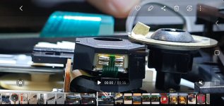
@elpossa It appears from your video od the PU lens attempt to focus that it won't sweep all the way through its focus range. There is no outward travel of the lens, which is why it wouldn't start spinning the disc. The focus offset is likely the issue and possibly the servo output to the focus coil. It may be a bad servo drive transistor or the coupling capacitor / feedback loop. Also advise to check the spindle height, but the focus issue would be independent of this and improper spindle height would usually result in intermittent skipping at the end of the focus range. This can be masked by the lack of focus travel range.
You're supposed to use an oscilloscope to monitor the focus drive. You'll see the focus search range, DC coupling on the 'scope.
There are no coupling capacitors in focus or tracking servos. They have to respond at DC. Some focus servos run with an offset of about +100 mV, depends on machine and head.
There are no coupling capacitors in focus or tracking servos. They have to respond at DC. Some focus servos run with an offset of about +100 mV, depends on machine and head.
Its an interesting question as to what is the correct height and its something I've never really given that much thought over.
There has to be a 'sweet spot' and although there will be a range over which it all works OK I would imagine only one point for the height setting will return a correctly sized as well as sharply focused spot back onto the photo diode array.
There has to be a 'sweet spot' and although there will be a range over which it all works OK I would imagine only one point for the height setting will return a correctly sized as well as sharply focused spot back onto the photo diode array.
Hi Karl,
As explained to me by Japanese engineers way back in time, you want the lens in it's mechanical centre. Gravity pulls the lens down, therefore there is a slight bias current up. They do not want that bias to be too high so you don't overheat the focus coil or drive electronics. Remember the driver transistors for the focus servo, one was a larger package? That was the positive (or negative if they flipped the polarity).
Of course, you want it in the centre mechanically so it can follow warped CDs. You never know if it will be dished, or if it is warped equally up and down. There are also slight differences in focal distance depending on the factory or production run. Not much at all, but we are talking about reflected light and you want to see a defined pit shape for a clean eye pattern.
On the NAD models 502 and successor models - equipped with KSS-210A - I observed in most cases, that only one of the focus servo driver transistors the PCB burned due to overheating.Hi Karl,
As explained to me by Japanese engineers way back in time, you want the lens in it's mechanical centre. Gravity pulls the lens down, therefore there is a slight bias current up. They do not want that bias to be too high so you don't overheat the focus coil or drive electronics. Remember the driver transistors for the focus servo, one was a larger package? That was the positive (or negative if they flipped the polarity).
Of course, you want it in the centre mechanically so it can follow warped CDs. You never know if it will be dished, or if it is warped equally up and down. There are also slight differences in focal distance depending on the factory or production run. Not much at all, but we are talking about reflected light and you want to see a defined pit shape for a clean eye pattern.
Due to the changed character of plastic suspension of the lens (due to aging) gravity pulled the lens down too much and the necessary balancing current was too high for the transistor.
Replace the laser unit was the usual way - I replace the burned transistor by a TO132 version (either BD139 or BD140) and use additional a small heat sink.
On CD-Player models with laser units with metal wire lens suspension (e. g. Sanyo SF-91) I haven't observe such unwanted effects.
- Home
- Source & Line
- Digital Source
- Sony CDP790 and KSS240 Restoration Project