This time the distortion could very well be caused by gain differences between the two different Dacs.In this latest configuration, as I see it, it would be possible to verify if it indeed was a timing difference that produced that spectrum, by inserting a variable time delay in the LE to one of the TDA1541A and then watch what happens when this time delay is varied.
Is it possible to make such a variable time delay easily?
Perhaps it would be easiest to insert a known non variable timedelay to the other TDA1541A so the timing between the to could go from + delay to - delay?
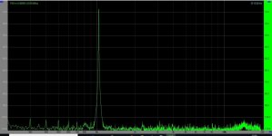
With 2.5% gain difference and zero timing difference I get the image below.
Hans
Attachments
First, this could be verified by changing one of the TDA1541A and if the spectrum is the same, it would be unlikely that this was the case , right?This time the distortion could very well be caused by gain differences between the two different Dacs.
With 2.5% gain difference and zero timing difference I get the image below.
Hans
Second, what does Phillips say about chip to chip variation on gain?
Third, do you know an easy way to make the variable time delay?
I am away from aroun 12:30 today, so nothing much happens here today.
1) Tuning the output magnitude would be a better idea, then you have the direct prove of a gain difference.First, this could be verified by changing one of the TDA1541A and if the spectrum is the same, it would be unlikely that this was the case , right?
Second, what does Phillips say about chip to chip variation on gain?
Third, do you know an easy way to make the variable time delay?
I am away from aroun 12:30 today, so nothing much happens here today.
2) Philips specifies a full scale current of 4mA +/- 15%, so that seems to be the gain difference between Dac's
3) An easy way for making a (variable) time difference is a S&H, but I think using two Dac's and tune them is a far better idea.
Hans
Last edited:
1) Tuning the output magnitude would be a better idea, then you have the direct prove of a gain difference.
2) Philips specifies a full scale current of 4mA +/- 15%, so that seems to be the gain difference between Dac's
3) An easy way for making a (variable) time difference is a S&H, but I think using two Dac's and tune them is a far better idea.
Hans
Hans,
How would you suggest to tune the amplitude. The one suggested by John, does not work. He suggested to put 150 Ohms on each of the two outputs (+ and -) and then sample the signal with two 1 Kohm resistors and then trim the 150 Ohm I/V resistors . Yhis does not work. The two outputs have to be conneceted directly. See post #7093-7094 and 7095.
I have simulated what John has suggested and compared the result to a perfect single +/- 4mA Dac.Hans,
How would you suggest to tune the amplitude. The one suggested by John, does not work. He suggested to put 150 Ohms on each of the two outputs (+ and -) and then sample the signal with two 1 Kohm resistors and then trim the 150 Ohm I/V resistors . Yhis does not work. The two outputs have to be conneceted directly. See post #7093-7094 and 7095.
I1 represents this perfect +/-4mA Dac, producucing output V(out75).
I2 is the negative going Dac, producing signal V(n002) and I3 the positive Dac, giving V(n003)
In the upper halve of the image, I have given Dac I2 a 4mA max output current and the other Dac I3 5mA.
Resistor R2 has already been adjusted from 150 to 120 Ohm to get the proper output swing, but as you can see, beween the green curve from the ideal Dac and the Blue curve from the compensated Dac there is still an offset that has to be adjusted.
By adjusting R5 from 2850 to 2280 Ohm, the offset has been adjusted and the blue curve V(out150) fits again perfectly on the green curve V(out75).
So you have to adjust two resistors.
Hans
Attachments

I have simulated what John has suggested and compared the result to a perfect single +/- 4mA Dac.
I1 represents this perfect +/-4mA Dac, producucing output V(out75).
I2 is the negative going Dac, producing signal V(n002) and I3 the positive Dac, giving V(n003)
In the upper halve of the image, I have given Dac I2 a 4mA max output current and the other Dac I3 5mA.
Resistor R2 has already been adjusted from 150 to 120 Ohm to get the proper output swing, but as you can see, beween the green curve from the ideal Dac and the Blue curve from the compensated Dac there is still an offset that has to be adjusted.
By adjusting R5 from 2850 to 2280 Ohm, the offset has been adjusted and the blue curve V(out150) fits again perfectly on the green curve V(out75).
So you have to adjust two resistors.
Hans
Well there must be something wrong with the assumptions and simulations, because it is not working like that in the real world. It is unfortunate , that I apparently is the only one on the planet, that , for the time being, has a working version of a Signed Magnitude TDA1541A , so nooen can confirm my findings. I urge the mebers here that find it interesting to build a prototype of it and see how it actually works.I have simulated what John has suggested and compared the result to a perfect single +/- 4mA Dac.
I1 represents this perfect +/-4mA Dac, producucing output V(out75).
I2 is the negative going Dac, producing signal V(n002) and I3 the positive Dac, giving V(n003)
In the upper halve of the image, I have given Dac I2 a 4mA max output current and the other Dac I3 5mA.
Resistor R2 has already been adjusted from 150 to 120 Ohm to get the proper output swing, but as you can see, beween the green curve from the ideal Dac and the Blue curve from the compensated Dac there is still an offset that has to be adjusted.
By adjusting R5 from 2850 to 2280 Ohm, the offset has been adjusted and the blue curve V(out150) fits again perfectly on the green curve V(out75).
So you have to adjust two resistors.
Hans
Anyhow , I did the same experiment with two 1 Kohm resistors from each output (+and -) now on the board modified to have one TDA1541A handling the positive halves and the other the negative halves of the L and R signal.
And the result was the same as described in post #7093-7094 and 7095.
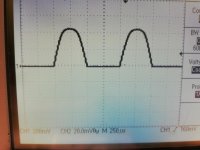
So to try to find an explanation for this behavior, and show how strange it behaves, take a look at this:
Pic 1:
This is the how it handles a FS , with one 150 Ohm on each output (resulting in 75 Ohm when shorting the outputs as John says), a 1,45 kOhm to 6,25V Vcc and the two outputs shorted together.
So about 4 mA ( well 4,3 mA) bias and that is all fine and good.
But what happens if I separate the two outputs?
Pic 2:
This is the DAC output from the DAC that handles the positive portion of the digital numbers. Now with 150 Ohm to ground AND still with 1,45 kOhms to Vcc alas a bias of 4,3 mA to only this DAC (if I chance the value, the baseline is no longer 0V)
Pic 3 :
This is the DAC output from the DAC that handles the negativ portion of the digital numbers. Now wit 150 to ground and NO bias.
Attachments


Let me know if anyone is willing to help progress the work on signed magnitude board. I have several boards from the first revision that kolby is using and I will send them for free just to get the issues sorted out.
I almost finished the second revision, but would like to be sure that there is no general design flaw with signed magnitude mode.
So please let me know if you are willing to help.
I almost finished the second revision, but would like to be sure that there is no general design flaw with signed magnitude mode.
So please let me know if you are willing to help.
Thank you Hans for taking so much time to look at my problem.Well there must be something wrong with the assumptions and simulations, because it is not working like that in the real world.
No thanks Koldby.
Anyhow, differences between simulations and the real world are nonsense.
The assumptions may be wrong, but tell me what's wrong, I wouldn't know.
Are you sure the RCA connector isn't again frustrating the signal like it did before ?
What is wrong is that you did not split the 1.45kOhm into two 2.9kOhm to each output.Pic 1:
This is the how it handles a FS , with one 150 Ohm on each output (resulting in 75 Ohm when shorting the outputs as John says), a 1,45 kOhm to 6,25V Vcc and the two outputs shorted together.
So about 4 mA ( well 4,3 mA) bias and that is all fine and good.
But what happens if I separate the two outputs?
Pic 2:
This is the DAC output from the DAC that handles the positive portion of the digital numbers. Now with 150 Ohm to ground AND still with 1,45 kOhms to Vcc alas a bias of 4,3 mA to only this DAC (if I chance the value, the baseline is no longer 0V)
Pic 3 :
This is the DAC output from the DAC that handles the negativ portion of the digital numbers. Now wit 150 to ground and NO bias.
You simply did not follow my instructions from the simulation.
Hans
Thank you Hans for taking so much time to look at my problem.
No thanks Koldby.
Anyhow, differences between simulations and the real world are nonsense.
The assumptions may be wrong, but tell me what's wrong, I wouldn't know.
Are you sure the RCA connector isn't again frustrating the signal like it did before ?
What is wrong is that you did not split the 1.45kOhm into two 2.9kOhm to each output.
You simply did not follow my instructions from the simulation.
Hans
I am very sorry if I haven't said how much I appreciate your work on this matter and I am very sorry if I sound like I do not. It must be that English is not my native languish, because I have no intention to be rude or anything like that. If I make mistakes in my measurements I am again very sorry. That was why I said that I wished someone else had this circuit in real world to compare with my findings or rectify the way I do it. I think I have on may occasions said that I am not the expert here, but I have to publish my findings, however wrong they are, to get anywhere .
Again sorry if it sounds like I am criticizing you or anyone else.
Personally , I think the remark:
Are you sure the RCA connector isn't again frustrating the signal like it did before ?
Was not called for , but then again, maybe I am too sensitive.
Did you read the last part of my posting.I am very sorry if I haven't said how much I appreciate your work on this matter and I am very sorry if I sound like I do not. It must be that English is not my native languish, because I have no intention to be rude or anything like that. If I make mistakes in my measurements I am again very sorry. That was why I said that I wished someone else had this circuit in real world to compare with my findings or rectify the way I do it. I think I have on may occasions said that I am not the expert here, but I have to publish my findings, however wrong they are, to get anywhere .
Again sorry if it sounds like I am criticizing you or anyone else.
Personally , I think the remark:
Are you sure the RCA connector isn't again frustrating the signal like it did before ?
Was not called for , but then again, maybe I am too sensitive.
You used only one 1.45k resistor instead of two 2.9k resistors, each side having their own pull up resistor.
That’s what you have done wrong.
Hans
And of course you were right. I just tried it and it looks like that was the issue.Now I face another problem, I think. How do I trim the bias resistors?Did you read the last part of my posting.
You used only one 1.45k resistor instead of two 2.9k resistors, each side having their own pull up resistor.
That’s what you have done wrong.
Hans
If I just put in the double value in each DAC the distortion is much worse with a lot of uneven order distortion.I have tried to put in trimmers instead, but they interact as one could imagine. I have just broken my left little finger in a mountain bike crash, so it slows me down 😱
Therefore no pics.
O.k. you are a further step in the right direction.And of course you were right. I just tried it and it looks like that was the issue.Now I face another problem, I think. How do I trim the bias resistors?
If I just put in the double value in each DAC the distortion is much worse with a lot of uneven order distortion.I have tried to put in trimmers instead, but they interact as one could imagine. I have just broken my left little finger in a mountain bike crash, so it slows me down 😱
Therefore no pics.
Now you must replace one of the two 150Ohm resistors by a 47Ohm pot in series with a 127Ohm resistor.
With this setup you can get as wel less gain and also more gain, depending on the mismatch.
This pot MUST be a ten turn pot, since 1e-4 mismatch is already visible, so it's a delicate job.
Maybe a 22Ohm ten turn pot plus 139Ohm is even better when mismatch is not too large.
Succes,
Hans
Yes that is what I must do in order to trim the I/V resistors, but how do I trim the bias resistors? I already have ten turn potmeters there, but I have problems with trimming those to something that makes the spectrum the same as it were with the two outputs shorted. I believe this is the first step before I trim the I/V resistors.O.k. you are a further step in the right direction.
Now you must replace one of the two 150Ohm resistors by a 47Ohm pot in series with a 127Ohm resistor.
With this setup you can get as wel less gain and also more gain, depending on the mismatch.
This pot MUST be a ten turn pot, since 1e-4 mismatch is already visible, so it's a delicate job.
Maybe a 22Ohm ten turn pot plus 139Ohm is even better when mismatch is not too large.
Succes,
Hans
And again I am very thankful for all your support and I understand if you want to back out of this journey at some point.
Cheers
koldby
Yes that is what I must do in order to trim the I/V resistors, but how do I trim the bias resistors? I already have ten turn potmeters there, but I have problems with trimming those to something that makes the spectrum the same as it were with the two outputs shorted. I believe this is the first step before I trim the I/V resistors.
And again I am very thankful for all your support and I understand if you want to back out of this journey at some point.
Cheers
koldby
When both bias resitors are 2k9, I would leave them for the time being and just concentrate on trimming the 150 Ohm.
After having reached a satisfactory situation, you can have a look at the combined output offset at the junction of the two 1 k resistors.
When that is too far off, then comes the point that a bias resistor could be adjusted.
But in all honesty, I very much doubt whether that will be the case.
Hans
There’s a lot in this thread to digest - is 50 hz DEM clock superior to external DEM injection? I haven’t found much discussion comparing the two...
I’ve got an AYAII in simultaneous mode with external clock (driven by BCLK xfrom an Ian FIFO clock board) and am wondering if I should do the DEM mod...
I’ve got an AYAII in simultaneous mode with external clock (driven by BCLK xfrom an Ian FIFO clock board) and am wondering if I should do the DEM mod...
Nothing wrong with the 50Hz DEM. I'm comparing it to a standard TDA1541 implementation (+SAA7220P/B), a cheap ES9018K2M with custom low noise Vregs/ADA4898 I/V, and a Soekris DAM1021. All with TPA6120 HP-Amp and AKG K702.
@Koldby,
Have you made any progress in attempting to reduce THD ?
What still came to my mind, is that you can also use two tda1541’s in parallel, where you add one non shifted from dac 1 with a shifted channel from dac 2 for the upper signal halve and ditto for the lower halve. In this way you won’t have to tune anything, just lower 75 Ohm to halve it’s value and adjust the bias resistor also.
Hans
Last edited:
Hi Hans.@Koldby,
Have you made any progress in attempting to reduce THD ?
What still came to my mind, is that you can also use two tda1541’s in parallel, where you add one non shifted from dac 1 with a shifted channel from dac 2 for the upper signal halve and ditto for the lower halve. In this way you won’t have to tune anything, just lower 75 Ohm to halve it’s value and adjust the bias resistor also.
Hans
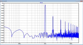
What a coincidence. I have just finished some trimming and measurements, and sat down to post it, when I saw your post 🙂
I am not sure I see what you want to do with two in parallel. Could you elaborate that a little or perhaps a schematic?
What I have done is this.
I put trimmers in both bias and I/V resistor in all 4 dac's (2 tda1541A) .
I initially adjusted all the I/V to excatly 150 Ohms and all the bias resistors to 2mA (3,15 K @ 6,3V).
The result was not very good. A lot of even and uneven harmonics. Then I adjusted the bias resistors (long time, they interact) and by this I could trim the uneven harmonics to -100dB. Then I trimmed the I/V. This reduces the even harmonics. Again interacting , not with the other dac but with the bias setting, and that makes perfect sense. I only had a 100 ohm trimmer (in series with a 100 Ohm resistor) and this is way to coarse. But I managed to get to the result in the picture. Pretty impressive right?
This is a -6 dB signal. It clips at 0dB.
Attachments
- Home
- Source & Line
- Digital Line Level
- Building the ultimate NOS DAC using TDA1541A