The best I know of today would probably be similar to the circuit shown in another thread, but with a high quality DC blocking film cap at the input (it has a cap, but the thread guys didn't figure out there is usually a jumper bypassing it on production units). Might also change the output stage a little, but its a VERY good sounding circuit: Pass HPA-1, what do we know? ...Some people who built their own version skimped on the power transformer based on their own simplified calculations. Mistake, IMHO. Pass labs went through six custom transformer iterations before settling on that core size and other construction details. The guys there all agreed it affected the sound. The HPA is also designed to work as line stage, in which case the HPA output is disabled.
EDIT: There is a review at Stereophile probably worth reading. Its also one of their main reference HPAs used for evaluating headphones.
EDIT 2: For best measurements, obviously use a good opamp circuit instead.
EDIT: There is a review at Stereophile probably worth reading. Its also one of their main reference HPAs used for evaluating headphones.
EDIT 2: For best measurements, obviously use a good opamp circuit instead.
Last edited:
Cheers Mark, I shall study that.
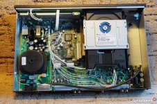
My own little project has hit another roadblock - I took the top off the Pioneer DVD-A160 and the way the thing is constructed, to even get a look at the component side of the main board would require totally disassembling the player, even removing the front panel, drive mechanism, everything but the power supply board, so I'm going to pass on using this machine, just too much hassle for the limited rewards. I shall find something better to work on, such as another Pioneer, either the DV-717 with it's twin PCM1716s or a another DV-737 with it's twin AD1854s.
My goal is to make three major upgrades:
- add a low jitter clock board with it's own isolated low-noise power supply
- add isolated low noise regulated supplies for the DAC & analogue stage
- replace the existing analogue output stage with an entirely new one
So now I just have to decide what sort of machine I want to chose to work on, maybe I'll go for a classic TDA1541 based one to see what all the fuss about the old 16-bit DAC is all about, or a player with a pair of PCM61s as that chips is also spoken of fondly. My current thinking leans more towards finding something which has a pair of modern DAC chips in it like the Pioneer DVD players I mentioned.
While looking at DVD players last night, an ARCAM DV88+ was listed for 25 quid BIN, so I immediately snapped it up. It had only been listed a few minutes, but for that price, I was having it.
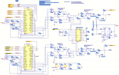
The DAC & output stage of the DV88 looks to be rather excellent,– dual WM8740s, one OPA2134 per channel output stage, discrete LFP, relays instead of muting transistors (ain't that a rarity!), isolated +/-12V supplies for OPA2134s, isolated +5v supplies for DACs, SILMIC & CERAFINE caps, hard to see much there that needs to be tweaked or upgraded.
Now I have this ARCAM to play my disks, I can really take my time with whatever DIY project I decide to build.
Attachments
Ian.
Arcam looks to have potential. I have a Cambridge Audio Dacmagic. The later smaller form factor thing. Same dacs as the DV88. I've done a few mods to that and it absolutely transformed it. Bypassed a lot of the output stage as it runs very low DC offset. Replaced 3 pjn regs for tps7a4701 type 3 pin replacements. Wima bypass over opamp.pins. Huge improvement.
But they're is also something to these old dac chips. Currently listening to Miros AD1862 and it is amazing for the simple build. I also have in my collection cheap Marantz and Philips CDs with tda1541 and 1549. Sound great.
That's good to know Jim, cheers, exactly the sort of help and advice I need!
I'll have to check, but I think the ARCAM is using 78xx regs, so I could definitely improve things there with more modern parts. I've got loads of polypropylene, tanatalum and OSCON caps in my stash so I can always make a few improvements there too.
I'll have to check, but I think the ARCAM is using 78xx regs, so I could definitely improve things there with more modern parts. I've got loads of polypropylene, tanatalum and OSCON caps in my stash so I can always make a few improvements there too.
Last edited:
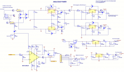
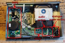
The power supply arrangements in the DV88 could certainly be improved, it uses an LM317/337 combo to provide the +/-12v for the OPA2134s in the output stage, a pair of LM317s to provide +5v to each of the WM7804 DAC chips and a pair of 7805s to power the clock and clock buffer.
Attachments
Before you invest in another DVD player, have you considered a Blu-ray player, some have very low jitter. But a warning - I bought a sony Blu-ray to play using the SPDIF out to a DAC, but it goes mental whenever I play Zep or RUSH, I have no idea why, the both play fine ( via SPDIF ) on my old Rotel CD player , it could be I've got the settings wrong on the sony, it could be a copyright issue ( sony being a record company ).
Yeah, I've looked at some Blu-ray players, not found any that can be had for an affordable price that have DACs and output stages comparable to the best DVD players. Maybe in a few years some of the early high end Blu-ray players will be available dirt cheap. The best Blu-ray player I looked at had a similar setup to the Arcam DV88 - a pair of WM8740s and a pair of OPA2134s in the output stage. It actually had a total of 8 WM8740s, one for each channel of the 7.1 system.
Last edited:
Using separate regulators for the dac chip analog and digital sections may help too. Digital supply for digital, and possibly something more suited to analog for that part. However, sometimes the clock circuitry is actually considered part of the analog part of the dac. Clock on its own regulator may help too if the clock is good enough to justify it.
For a good opamp power supply, already described how I have been doing it for AK4499 in another thread: ES9038Q2M Board ...Posts #7158 and #7162. Some local electrolytic power rail caps of your choice near the opamps may help bass.
The above and some Wima FPK2 bypass caps, or else 805 SMD acrylic film bypass caps, would probably be pretty good.
Last edited:
The ARCAM has a single +5V supply for each DAC chip, each regulated by it's own LM317, labelled 5V DAC L and 5V DAC R.
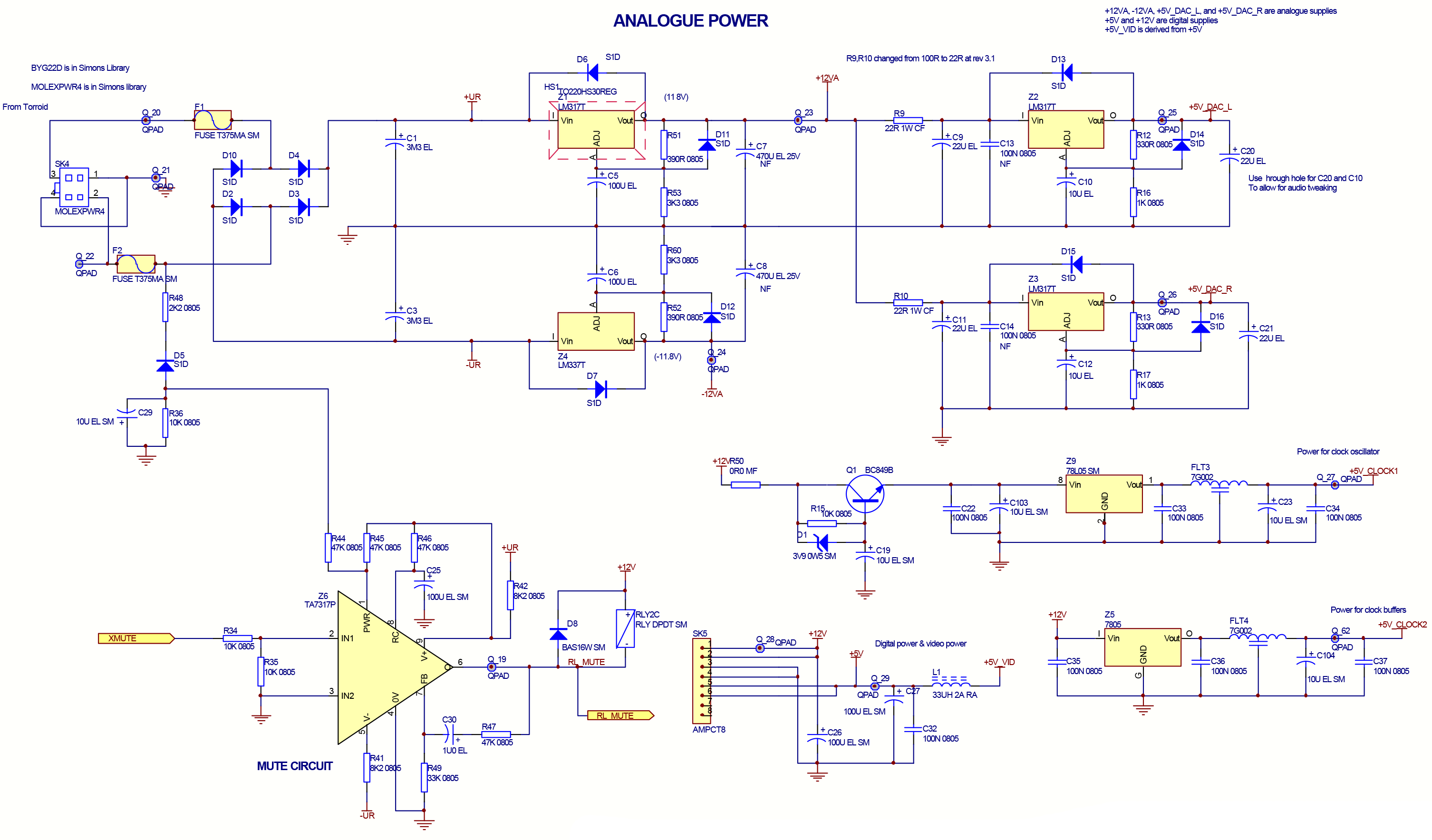
Each DAC chip has four 5v inputs - VCC, AVDDR, ACDDL, DCDD and MODE. I think MODE is just to put the chip into differential mono mode so we don't need to worry about that.
So do you think I should use more than one supply for each DAC chip? If so, how would you arrange the supplies - one for VCC and one for the other three, or give all four their own individual supplies?
There looks to be plenty of room for adding more elaborate power supply arrangements for the DACs - the bundle of cables running along the bottom from the PSU board to the bottom right corner is probably carrying +/-12V, +5V and GND on it's four pins and the LM317/337s that regulate the supplies for the DACs and the output stage opamps are located on the bottom right. There's a load of space along the right hand side of the case where I could place power regulation and perhaps a small trafo.
Attachments


Last edited:
So it doesn't have an SMPS....bonus. unless the black round thing is a dc convertor?
I would definitely suggest adding separate rails to the digital (DVDD) and analogue (AVDD L/R) rails. I see they have a ferrite bead to split these in the Arcam so I don't know how big an improvement this would actually bring, but as you know generally these rails on separate regs is a good thing.
The regs I would use are 7x0x series compatible and so won't be a pin for pin swap for the LM3x7.
Good preforrmance can be had from 3x7s though. See the big 317/337 with denoiser thread. Just recently Trileru has developed 3 pin drop on replacements with discrete components. However if you struggled with the soldering of your dac chips this may not be feasible for you. Maybe the denoiser components could be tacked onto the pcb kind of point to point. Not sure! I believe using 220uf Cadj on 317 is a good start. You seem to have 100uf.
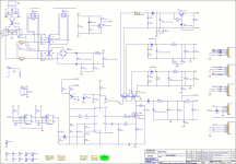
I add the schematic of what CA did in the later dacmagic, not as good as the Arcam by the looks.
I would definitely suggest adding separate rails to the digital (DVDD) and analogue (AVDD L/R) rails. I see they have a ferrite bead to split these in the Arcam so I don't know how big an improvement this would actually bring, but as you know generally these rails on separate regs is a good thing.
The regs I would use are 7x0x series compatible and so won't be a pin for pin swap for the LM3x7.
Good preforrmance can be had from 3x7s though. See the big 317/337 with denoiser thread. Just recently Trileru has developed 3 pin drop on replacements with discrete components. However if you struggled with the soldering of your dac chips this may not be feasible for you. Maybe the denoiser components could be tacked onto the pcb kind of point to point. Not sure! I believe using 220uf Cadj on 317 is a good start. You seem to have 100uf.
I add the schematic of what CA did in the later dacmagic, not as good as the Arcam by the looks.
Attachments

Last edited:
It has an SMPS, the big round thing is a toroidal trafo, this SMPS board supplies +12v to what in the manual is called the analogue power section, which is where the LM317/337s and 7805s are.

What about using a discrete Zener+emitter-follower regulator such as shown on Werner Ogier's website? He shows noise plots that have a lot less noise than an LM317:
Simple Voltage Regulators Part 1: Noise - [English]
What about using a discrete Zener+emitter-follower regulator such as shown on Werner Ogier's website? He shows noise plots that have a lot less noise than an LM317:
Simple Voltage Regulators Part 1: Noise - [English]
Attachments

If the 220 uf measure better in theory, it sounds way better without it in real life cause it sucks all the transcient... you should use also a Darlington there if for an I V or a an oap. better at the end of the load a small decoupling if needed, film type smd (PPS) or radial (MKT, less good than the previous but troughole)
my two cents
LM317 and 7805 are perfectly fines, just put at the output leg of the 78 reg type something like a 47 to 220 uf of an old cap (the used one of old cd player for that job are perfect, even more if Nichicon Sx marked, blue ones) to have some Z... At the opposite of the input leg to Gnd you can put a fresh low esr cap of your convenience...
In this case there is a data sheet available for the dac chips. This might be an opportunity to start learning how to read one 🙂
It contains some info about powering the chips that will help answer some of your questions. For the questions that remain unclear, or for questions about interpreting the data sheet, we can try to help.
It contains some info about powering the chips that will help answer some of your questions. For the questions that remain unclear, or for questions about interpreting the data sheet, we can try to help.
Good advice from diyiggy about improving the voltage regulator.
Best to replace the SMPS with linear, of course.
Best to replace the SMPS with linear, of course.
Last edited:
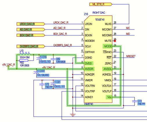
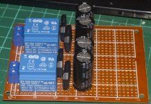
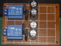
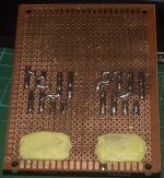
I've built a set of linear supplies for the DAC chips, as small as I could make them, using two encapsulated trafos that each sport a pair of 6v 175mA secondaries giving a total of four 6v 175mA lines on a PCB measuring just 7x9cm (2 5/8 x 3 1/2 inches). I've potted the 250v bit in epoxy putty for safety purposes and used the largest caps I had that would fit - 16v 2200uF as smoothing caps. I haven't fitted any regulators to the board yet, but there is ample room left for them.
So using this board I can provide two 5v regulated lines to each of the two DAC chips.
One thing I might have done better is the rectifiers - I used RBP310 bridges as they take up very little space, but I have read that Schottky diodes have less noise. I suppose I can add a couple of snubber caps to the RBP310s to reduce noise, I honestly don't know how noisier the bridges will be vs a quartet of Schottkys.
Attachments

Looks nice Ian, just check those trafos give you enough headroom. They won't provide 175ma . 6v and 0.175va is more like 30ma which will then be lowered by approx 40percent once it is rectified.
Someone please correct if I'm wrong.
Nice little psu though. I doubt you will hear s difference with a change to Schottkys. But there are those whom can tell the difference
Someone please correct if I'm wrong.
Nice little psu though. I doubt you will hear s difference with a change to Schottkys. But there are those whom can tell the difference
Oh balls, I misread the label on the trafos, thanks for catching that ****-up.
6/0.175=34.28 so my mini trafos are putting out just under 35mA per secondary winding.
Losing 40% of the 35mA to rectification leaves just 20-21mA.
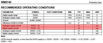
Checking the datasheet for the WM8740, it gives the analogue current consumption as 13mA typical and the digital current consumption at 19mA typical, it doesn't give any max figures for current.
So I might get away with using these trafos, there isn't much headroom.
6/0.175=34.28 so my mini trafos are putting out just under 35mA per secondary winding.
Losing 40% of the 35mA to rectification leaves just 20-21mA.
Checking the datasheet for the WM8740, it gives the analogue current consumption as 13mA typical and the digital current consumption at 19mA typical, it doesn't give any max figures for current.
So I might get away with using these trafos, there isn't much headroom.
Attachments
Last edited:
I guess all I can do is try them and see what happens.
It just occurred to me that whatever regulators I use will also consume some current.
According to the datasheet, a 7805 uses 5mA.
Oh bugger....
It just occurred to me that whatever regulators I use will also consume some current.
According to the datasheet, a 7805 uses 5mA.
Oh bugger....
Last edited:
- Home
- Source & Line
- Digital Line Level
- CD player upgrade project