Thank you, I'll make some enquiries to see if a small group buy for assembled boards will be viable.
Just to update - I will not progress a group buy for assembled boards as I have now made arrangements to have a board assembled for me - sorry for any disappointment.
Just to update - I will not progress a group buy for assembled boards as I have now made arrangements to have a board assembled for me - sorry for any disappointment.
cannot guarantee anything. but if i will be succesfull in the build i may offer the same thing "as a service".
I have everything needed on my way. and i can report the outcomes very soon !
If you are pleased with the results are you considering modifying your DSD Stik decoder to integrate it closely - IIRC you boards are currently designed to use a BBB?
who knows

i have no plan for the future... i am enjoying the journey
I was send gerber and order this pcb.
I hope the future it will measure the sampling frequency input, then choose TCXO 44.1K / 48Khz family to Reclock - it mean are no need the MCLK input.
And the Mute, DSD_OE pin at output will work independently without depending Mute, DSD_OE pin base on input.
We're have a SRC Universal, alright
I hope the future it will measure the sampling frequency input, then choose TCXO 44.1K / 48Khz family to Reclock - it mean are no need the MCLK input.
And the Mute, DSD_OE pin at output will work independently without depending Mute, DSD_OE pin base on input.
We're have a SRC Universal, alright
Last edited:
Finally I'm using dynamic partial dithering. The dithering levels were chosen experimentally because I don't know how to calculate them correctly yet.
Just out of curiosity, what do you mean by dynamic dithering (what's the difference with static dithering) and what kind of dither probability distribution do you use? Rectangular, triangular or just a few equally probable discrete values?
success
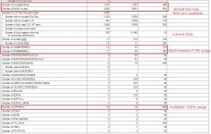
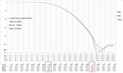
I have successfully squeezed my xc6slk25 version into xc6slx9(pic. 1). The differences between them(post#30) are an oversampling stage and two 5th order DSMs. Xc6slx9 has a half-size FIR because of time multiplexing, which results in a bit large HF droop(pic. 2). More than 0 dB(+0.1dB) doesn't mean clipping because the gain of oversampling FIR is almost -8dB; -5dB for DSM stability and -3dB anti-ISO. I guess -3dB is enough to guarantee ISO-free. One advantage of the FPGA-based preprocess is easy to implement anti-ISO logic. I'm sure ISO is a more dominating factor than clock jitter as long as I have experienced it.
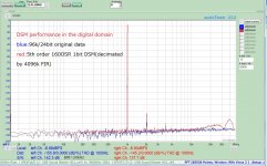
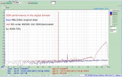
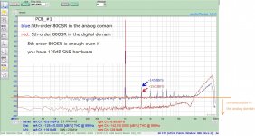
Xc6slx9 version has an option to select 160OSR or 80OSR; EEPROM 1pin=open:160OSR,EEPROM 1pin=GND:80OSR. Pic.3 is the digital domain performance of 5th order 160OSR. There is small quantization noise above 20kHz; almost no degradation. Pic.4 is 80OSR. You can see large quantization noise if you compare it with 160OSR. But what you need is the analog domain performance, not the digital. Even if you have excellent hardware(120dB SNR), 80OSR is enough in the analog domain;pic.5. High OSR means high sampling frequency, which ends up poor performance in the analog domain. I prefer 80OSR to 160OSR, though you have an option which to use.
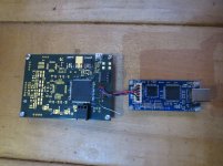
Xc6slx9 has a different pin assignment from olo111's PCB because the development was done with a spare PCB(pic.6) having an xc6slx9 footprint. It's a straightforward process to change the pin assignment when his PCB is ready. Then, I will post the final version.
I have successfully squeezed my xc6slk25 version into xc6slx9(pic. 1). The differences between them(post#30) are an oversampling stage and two 5th order DSMs. Xc6slx9 has a half-size FIR because of time multiplexing, which results in a bit large HF droop(pic. 2). More than 0 dB(+0.1dB) doesn't mean clipping because the gain of oversampling FIR is almost -8dB; -5dB for DSM stability and -3dB anti-ISO. I guess -3dB is enough to guarantee ISO-free. One advantage of the FPGA-based preprocess is easy to implement anti-ISO logic. I'm sure ISO is a more dominating factor than clock jitter as long as I have experienced it.
Xc6slx9 version has an option to select 160OSR or 80OSR; EEPROM 1pin=open:160OSR,EEPROM 1pin=GND:80OSR. Pic.3 is the digital domain performance of 5th order 160OSR. There is small quantization noise above 20kHz; almost no degradation. Pic.4 is 80OSR. You can see large quantization noise if you compare it with 160OSR. But what you need is the analog domain performance, not the digital. Even if you have excellent hardware(120dB SNR), 80OSR is enough in the analog domain;pic.5. High OSR means high sampling frequency, which ends up poor performance in the analog domain. I prefer 80OSR to 160OSR, though you have an option which to use.
Xc6slx9 has a different pin assignment from olo111's PCB because the development was done with a spare PCB(pic.6) having an xc6slx9 footprint. It's a straightforward process to change the pin assignment when his PCB is ready. Then, I will post the final version.
Attachments
i have a very little grasp on theese topics... but as far as i understand yours could be a different sythesis for the olo pcb ?
Do you advice better performances from it ? sorry, but i guess i need a down-to-the-ground version of your (surely accurate) explanation
i have gathered all the parts/pcb to make the olo iteration. I guess by this weekend i have something working on my bench to test it out.
thanks
Do you advice better performances from it ? sorry, but i guess i need a down-to-the-ground version of your (surely accurate) explanation
i have gathered all the parts/pcb to make the olo iteration. I guess by this weekend i have something working on my bench to test it out.
thanks
i have a very little grasp on theese topics... but as far as i understand yours could be a different sythesis for the olo pcb ?
Do you advice better performances from it ? sorry, but i guess i need a down-to-the-ground version of your (surely accurate) explanation
i have gathered all the parts/pcb to make the olo iteration. I guess by this weekend i have something working on my bench to test it out.
thanks
Yes, It's another synthesis for olo111's PCB. The attached has the same pin assignment as olo111. You can enjoy it unless the reassignment is incorrect.
Attachments
That's good to try ! ThanksYes, It's another synthesis for olo111's PCB. The attached has the same pin assignment as olo111. You can enjoy it unless the reassignment is incorrect.
You said that one difference is the fact that yours oversample... But If red correctly... Also the original version does it.
I misunderstood ?
Hi xx3stksm!
Excellent work, congrats!
Did you use only one output tap for measurments?
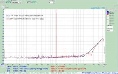
I'm afraid I can't get what you mean. If you think one DSM channel is replaced with a 4096 length decimation filter for measurement purposes, it's almost correct. The decimation filter from 1bitDSM to PCM doesn't require a multiplier but several adders. But unfortunately, two 5th order DSMs with one local FB and a 4096 decimation filter can't coexist because of the small capacity of xc6slx9. One 5th order DSM with one local FB, One 5th order DSM without local FB, and a 4096 decimation filter are possible. So, measurement of 5th order DSM with one local FB is done in such condition. The final version(xc6slx9.zip) includes two 5th order DSMs with one local FB, no 4096 decimation filter. Attached is the difference between with and without.
Attachments
That's good to try ! Thanks
You said that one difference is the fact that yours oversample... But If red correctly... Also the original version does it.
I misunderstood ?
An oversampling process is a bit shrank because of a small resource of xc6slx9. But as long as the reassignment of pins is correct, no problem. I hope your happy weekend.
I think anyone will be very happy if DSD_On (pin 7), Mute (pin 11), switch external clock (pin 1) and sample rate indicator F0-F1-F2-F3 (pin 17-18-19-20) at output port can operating freely without dependence by 20 pin Input.
So, we're can use it for Rpi without MCLK or other I2S.
So, we're can use it for Rpi without MCLK or other I2S.
Very interesting project.
Ian
I want this project embedded into your FifoPi Q3. Perfectly ��
Yes, It's another synthesis for olo111's PCB. The attached has the same pin assignment as olo111. You can enjoy it unless the reassignment is incorrect.
Thanks !
can you summarize the main differences between your version and the "official" one ?
i think oversampling is done in both cases.
you use 2x 5th order modulators vs 1x 7th order ?
I want this project embedded into your FifoPi Q3. Perfectly ��
I am not sure it will fit to the FPGA that fifoPi Q3 uses
maybe is matter for Q4.
Thanks !
can you summarize the main differences between your version and the "official" one ?
i think oversampling is done in both cases.
you use 2x 5th order modulators vs 1x 7th order ?
Xc6slx9 version is 256length FIR for 192k, 512length FIR for 96k, 1024length FIR for 48k, and two 5th order DSMs. Xc6slx25 is 1024length FIR for 96k, one 4th order DSM, and one 5th order DSM. Xc6slx9 has only one oversample module because of a small size. That's why xc6slx9 has a half-size FIR with time-multiplexing.
- Home
- Source & Line
- Digital Line Level
- Simple DSD modulator for DSC2