Ok, then no way.
In the FIFO Lite the latency is configurable setting the portion of the SRAM to be used, from 8Mbit (max) to 100Kbit (min), but the minimal latency will be at least 30-40 ms.
As the calculations in the other thread show, with a decent source clock this amount of buffering isn't necessary at all to prevent dropouts.
We cannot decrease the latency below 100Kbit, our approach is totally different, we don't care about long term clock stability because it's useless in digital to analog conversion.
We look for the best short term stability so we don't care about the oscillator Allan deviation.
We use SC-Cut crystals without an oven so the long term stability could be "not decent" and so a minimum buffer is needed.
Of course, our oscillators could be even perfect in long term stability adding an oven, but we have tested this way and there is no improvement in close in phase noise, so adding an oven does not worth because it adds complexity and costs.
What I mean is that in the top version you will use 0.001% resistors, capable of 18 bit precision, but if 24 bit precision can be achieved with calibration why bother?The top version of the DAC will keep long time development.
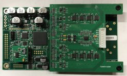
Substantially it's not only the DAC but the whole system including the front end (the top version of the FIFO).
The architecture is the same of the FIFO and DAC Lite, but with improved solutions in all the aspects.
For example we will use optic fiber cables to connect the dirty signals from the FIFO to the DAC, we will use different dividers for the LRCK, we will use different sine to square converters, the first 5 MSB of the DAC are thermometer decoded (instead of the first 3 MSB of the DAC Lite), and so on.
Maybe the main difference is that the FIFO Lite is a open system compliant with almost all DACs while the Top version is a closed system, the Top end of the FIFO works with the Top end DAC only, no way to use it with other DACs.
Sorry for all the questions
I got the 0.001% resistors some time ago before planning the digital calibration.
Moreover they are wirewound precision resistors with very low thermal drift so I'm curious to try them in the top end DAC.
I will do a comparison against the Susumu thin film resistors with higher tolerance, and maybe even against the Vishay Z-foil.
Moreover they are wirewound precision resistors with very low thermal drift so I'm curious to try them in the top end DAC.
I will do a comparison against the Susumu thin film resistors with higher tolerance, and maybe even against the Vishay Z-foil.
That will be an interesting comparison, I believe soekris DACs use Susumu RG for the MSBs.
Also from the cost reduction using higher tolerance resistors wouldn't it become viable to extend the thermometer decoding to more bits in the lite DAC or is there more to it?
Also from the cost reduction using higher tolerance resistors wouldn't it become viable to extend the thermometer decoding to more bits in the lite DAC or is there more to it?
Last edited:
The thermometer of the DAC Lite is the first 3 MSBs and the board is already very large.
To extend it to 4 MSBs I should add 32 resistors (8 for each rail of each channel) and 32 flip-flops.
The board will become too large.
Indeed the board of the top end DAC (first 5 MSBs thermometer decoded) will be dual mono to lower the size.
To extend it to 4 MSBs I should add 32 resistors (8 for each rail of each channel) and 32 flip-flops.
The board will become too large.
Indeed the board of the top end DAC (first 5 MSBs thermometer decoded) will be dual mono to lower the size.
Not for measuring the temperature.
The thermometer is the first section of the segmented ladder, the first 3 MSBs are thermometer like decoded (3 to 7).
The thermometer is the first section of the segmented ladder, the first 3 MSBs are thermometer like decoded (3 to 7).
Is there a thermometer in the DAM?
//
I meant in our DAC Lite, the DAM has the first 2 MSBs thermometer like decoded (2 to 3).
Um, I'm very curious what the result will be. Will you have any measurements? And will you have a listening test?
I will measure the phase noise before and after the upgrade.
And there will be a listening session to compare the result with and without the tweaking, since the boards easily allow to switch between the two options.
It will take a few time because we have to update the firmware of the FIFO Lite to manage the specific data protocol of the DAM1021.
And there will be a listening session to compare the result with and without the tweaking, since the boards easily allow to switch between the two options.
It will take a few time because we have to update the firmware of the FIFO Lite to manage the specific data protocol of the DAM1021.
Hi Andrea, is there a chance we could implement dual mono DAM1021 with your upgrade board and FIFO?
Ken
Ken
Hi Andrea, is there a chance we could implement dual mono DAM1021 with your upgrade board and FIFO?
Ken
Yes, the FIFO Lite has double output so you can drive the left and the right channel separately.
Does each output port able to configure as left and right channel individually?
No, the output connectors are predefined as left and right channels.
Measurements and listening session
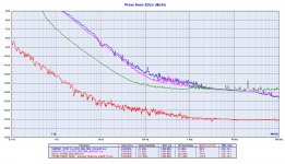
The phase noise performance of the DAM1021 are poor.
Not a big surprise since the Si514 is a poor oscillator.
A listening session of the DAM1021 has confirmed there is something wrong, it's not bad but it's far from a SOTA device.
I believe this means there is enough room to improve its sound quality implementing a well isolated FIFO buffer with very good oscillators.
Attachments
- The last measurement, the DAM LRCK needs to be scaled back from 3Mhz to 192k in order to be comparable?
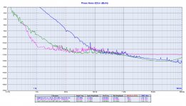
- The DAM spdif vs I2S - what was the driver for these? Same clocks or different? The DAM LRCK looks very similar despite different interfaces - at least for 44,1.
- As you only have one DAM, the DAM LRCK can have been done the same time... you know from the zfe measurements how much the DAM may very its frequency over 0-20 minutes - maybe the 48k measurements happen at a time when there was a lot of frequency adjustment as we see here that the spdif and i2s deviate from each-other which they didn't for 44,1.
- If you want to prove that the DAM fifo/DPPL is passing jitter, you need to use the same Fs, the same interface (i2s) but change the clocks driving the interface and measure on the actual interface so that it is clear what really hits the DAM - just pointing to a clock doesn't cut it - much can happen, as you know, between a clock/oscillator component and when data (+clock) is present the line...
If you can show measurements for say 2 or 3 different clocks (one really bad, one OK and one super) used to drive the interface towards the DAM and also show how the DAM LRCK is affected you have technical proof. Otherwise is just guessing.
//
- The last measurement, the DAM LRCK needs to be scaled back from 3Mhz to 192k in order to be comparable?
- The DAM spdif vs I2S - what was the driver for these? Same clocks or different? The DAM LRCK looks very similar despite different interfaces - at least for 44,1.
- As you only have one DAM, the DAM LRCK can have been done the same time... you know from the zfe measurements how much the DAM may very its frequency over 0-20 minutes - maybe the 48k measurements happen at a time when there was a lot of frequency adjustment as we see here that the spdif and i2s deviate from each-other which they didn't for 44,1.
- If you want to prove that the DAM fifo/DPPL is passing jitter, you need to use the same Fs, the same interface (i2s) but change the clocks driving the interface and measure on the actual interface so that it is clear what really hits the DAM - just pointing to a clock doesn't cut it - much can happen, as you know, between a clock/oscillator component and when data (+clock) is present the line...
If you can show measurements for say 2 or 3 different clocks (one really bad, one OK and one super) used to drive the interface towards the DAM and also show how the DAM LRCK is affected you have technical proof. Otherwise is just guessing.
//
There is nothing to scale, the comparison is between the incoming LRCK (RPI) and the output LRCK from the DAM1021 front end.
The frequency does not matter, the 595s are fed by that LRCK.
The switches aren't able to scale anything, they are clocked by the LRCK as is.
The only way to scale is to get the DAM1021 running at lower frequency.
IMHO nothing will change because the Si514 is a very poor oscillator as clearly indicated in the datasheet.
Indeed the datasheet specify the part for telecommunication application and therefore the jitter was measured with an integration bandwidth suitable for such that applications (starting from 12 kHz).
I have already described the sources in the designer's thread:
- AUNE X5S SD card player for S/PDIF
- RPI 4 standalone source for I2S
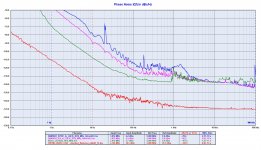
If you look at the x48 family plot you see a difference around 12-13 dB between the S/PDIF and the I2S sources.
The DAM1021 tracks the incoming phase noise and reflects it to the output.
All the phase noise measurements was 1 hour long so no error possible since the TimePod average the samples and discard the extremities.
Moreover the phase noise is short term stability measurement, so the long term fluctuation does not affect the phase noise.
The Allan Deviation measurement takes care about the long term stability but it's another thing (Rubiola.org for reference), and of course it's useless in digital audio since the long term stability does not affect the conversion.
I have nothing to prove, I have listened to this DAC for a few days and it was clear its sound quality is far from SOTA devices and even from the old TDA1541A.
I can listen to the TDA1541A all the day, while I get tire after half an hour listening to the DAM1021.
However the third plot clearly prove that the DAM is source dependent since there is 12-13 dB of phase noise difference betwen the different sources.
If the DAC was well isolated from the source the LRCK phase noise should be the same since it comes from a different time domain.
Of cource, all the 3 plots show a poor LRCK phase noise regardless of the source.
Last edited:
- Home
- Source & Line
- Digital Line Level
- Implementing a true FIFO buffer with low phase noise clock on the Soekris DAM1021 DAC