You feed a good clock to a PLL with a much worse clock and you claim that the good clock make the bad clock even much more worse.
//
Not my claim but measurements.
Anyway it's not a surprise, both negative effects are summed in the final result.
Poor isolation allows the incoming jitter to pass and poor master clock makes the output worse than the input.
The measurements look like they prove source dependency, which I think was the point.
How different sources can worsen jitter when the DAMs jitter swamps them is in unusual, but I dont see this is andrea's problem, rather just a problem he brought to light.
Is it because every possible kind of interference from source should be expressible with jitter?
So then maybe you think there could be a problem with the measurements?
No. I still don't know, what kind of filters are used. If there is no upsampling and no oversampling. There must be a very good solution, especially if you listen with AMT and Ion Tweeter. The question is serious. A NOS DAC would be something nice without the known errors. The measurement results are mainly a disaster in any case.Then you would say our DACs phylosophy is is outdated for the market?
The measurements look like they prove source dependency, which I think was the point.
How different sources can worsen jitter when the DAMs jitter swamps them is in unusual, but I dont see this is andrea's problem, rather just a problem he brought to light.
Is it because every possible kind of interference from source should be expressible with jitter?
So then maybe you think there could be a problem with the measurements?
Yes, the negative effects are all summed.
I don't believe there could be a problem with the measurements, the TimePod is a certified instrument now sold by Microsemi as 3120A model.
No. I still don't know, what kind of filters are used. If there is no upsampling and no oversampling. There must be a very good solution, especially if you listen with AMT and Ion Tweeter. The question is serious. A NOS DAC would be something nice without the known errors. The measurement results are mainly a disaster in any case.
The filter used in the TDA1541A DAC I have built for a friend is simply a parallel capacitor at the output, so 6 dB/oct low pass filter.
The irons in the tube ampli help limiting the bandwidth, they are pass-band filters so no risk that ultra high frequencies pass through.
So you could use the same filter/tube amp with the dam after your FIFO is used?
When I will make the comparison between the DAM1021 and the TDA1541A DAC reference I will use the setup of the friend, so yes I will use the same tube ampli.
For me I'm building a different ampli with the GM-70 DHT, also a tube ampli.
I don't like to apply negative feedback in the ampli so the tubes are the only way because they are linear devices while transistor and mosfet are non linear devices.
I will also build a solid state ampli as soon as I find the time (I already have all parts), but it will be a 16W output zero feedback transformer coupled ampli.
Originally Posted by TNT View Post
You feed a good clock to a PLL with a much worse clock and you claim that the good clock make the bad clock even much more worse.
//
No logic rains here. You own a fancy measurement equipment but your analysis of its output is not on the same level.
//
You feed a good clock to a PLL with a much worse clock and you claim that the good clock make the bad clock even much more worse.
//
Not my claim but measurements.
Anyway it's not a surprise, both negative effects are summed in the final result.
Poor isolation allows the incoming jitter to pass and poor master clock makes the output worse than the input.
No logic rains here. You own a fancy measurement equipment but your analysis of its output is not on the same level.
//
Last edited:
What are you talking about?
Do you think that the better incoming clock could cure the bad output clock?
Your knowledge about phase noise is very limited.
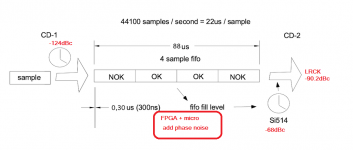
The plot is clear: RPI LRCK -124.8 dBc at 10 Hz from the carrier; DAM1021 LRCK -90.2 dBc at 10 Hz from the carrier.
You expected to read -124dBc even for the DAM?
I have suggest several times, study Rubiola.org.
Do you think that the better incoming clock could cure the bad output clock?
Your knowledge about phase noise is very limited.
The plot is clear: RPI LRCK -124.8 dBc at 10 Hz from the carrier; DAM1021 LRCK -90.2 dBc at 10 Hz from the carrier.
You expected to read -124dBc even for the DAM?
I have suggest several times, study Rubiola.org.
"What are you talking about?
Do you think that the better incoming clock could cure the bad output clock?"
No I have never suggested that. But you seem to think it can make it considerable worse.
//
Do you think that the better incoming clock could cure the bad output clock?"
No I have never suggested that. But you seem to think it can make it considerable worse.
//
Yes, exactly as measured.
If you don't trust the TimePod's measurements please ask Microsemi (or John Miles, the designer).
Or better study the phase noise principles.
If you don't trust the TimePod's measurements please ask Microsemi (or John Miles, the designer).
Or better study the phase noise principles.
You don't realise that the discussion is about how a FIFO and a DPLL works.
//
//
Attachments
Last edited:
No, you don't understand how the whole system works and you don't understand the basis of the phase noise.
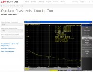
I attach the phase noise plot of the Si514 extracted from the Silicon Labs website.
The phase noise at 50 MHz (DAM master clock frequency is 49.152 MHz) is -99dBc at 100Hz from the carrier.
We are close to the 1/f3 region (Leeson equation) so add 30dB/decade and you get -69dBc at 10Hz from the carrier (vey poor oscillator).
Now subtract the theoretical 6dB for each division by 2 until 3.072 MHz, so 24dB.
Although in the real world it's a little different from the theory let assume the phase noise at 3.072 MHz is -69dBc - (-24dBc) = -93dBc at 10 Hz from the carrier (again poor oscillator, since our 6.144 MHz oscillator - double frequency - is -145dBc at 10 Hz from the carrier).
This is the theoretical better phase noise you can reach from the DAM1021 LRCK if the input time domain was well isolated from the FIFO time domain.
I have measured -90.2 dBc at 10Hz from the carrier, so around 3dB worse than the calculated value.
Would you dispute around 3dB?
Well, 3dB are the added phase noise by the FPGA and the micro and the beatings with the incoming jitter.
Attachments
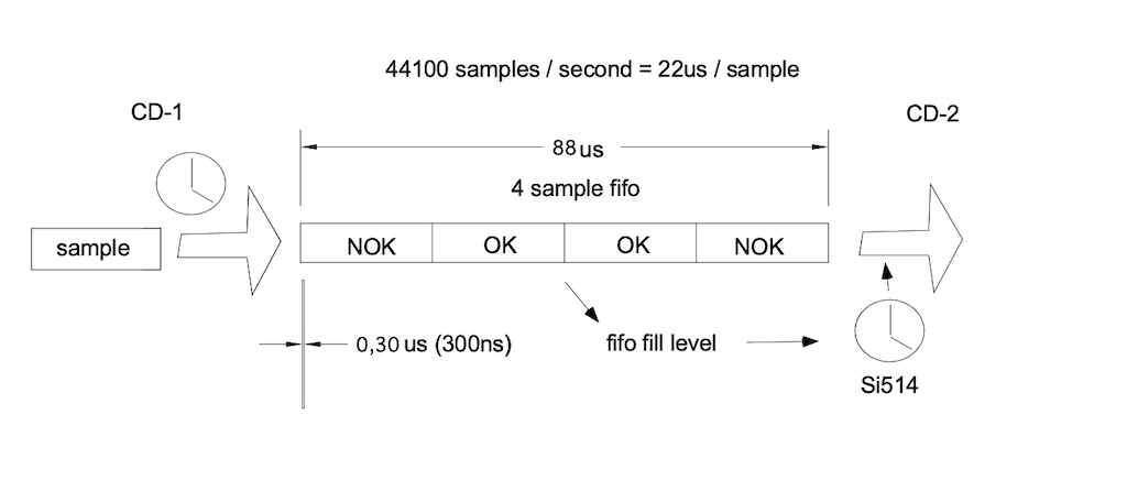
The "fifo fill level" in my picture is only software - its not in the "signal path" of the oscillator. This software orders frequency changes of the Si as a consequence of the fill level in the fifo. Do you think noise is added by an If statement in SW?
Your noise calculations look fine. So -90,2 dBc/Hz at 10Hz for LRCK driving the ladder - and this is including the addition from the fpga etc. At the ladder.
So how much of this -90,2 dBc/Hz at the ladder is coming from the incoming clock with -124dBc/Hz that you say contaminate the LRCK ?
//
Your noise calculations look fine. So -90,2 dBc/Hz at 10Hz for LRCK driving the ladder - and this is including the addition from the fpga etc. At the ladder.
So how much of this -90,2 dBc/Hz at the ladder is coming from the incoming clock with -124dBc/Hz that you say contaminate the LRCK ?
//
Attachments
"The "fifo fill level" in my picture is only software "
There are no "software" in the FPGA (field-programmable gate array), only "wired" logic blocks. These are dependent of system clock.
Field-programmable gate array - Wikipedia
"Logic blocks can be configured to perform complex combinational functions, or merely simple logic gates like AND and XOR. In most FPGAs, logic blocks also include memory elements, which may be simple flip-flops or more complete blocks of memory"
Well, where I come from, we call fpga code, software ;-)
But its still quite irrelevant - we have -90dB at the ladder - some of it is said to come from the primary side of the fifo - how much?
-130 dB + (-93dB) is -93 dB....
The fpga adds noise yes - but this is not the same as it is dependent or pass through stuff from the primary side.
//
But its still quite irrelevant - we have -90dB at the ladder - some of it is said to come from the primary side of the fifo - how much?
-130 dB + (-93dB) is -93 dB....
The fpga adds noise yes - but this is not the same as it is dependent or pass through stuff from the primary side.
//
Last edited:
If the FPGA logic is to track the source clock (instead of tracking a newly generated clock from a independant crystal) then by design whatever happens at the source clock side would somehow find it’s way through, no?
The DPLL logic of trying to follow the source clock by adjusting the Si, in itself these adjustments would be hunting up and down trying to keep track. This in itself would generate additional PN/jitter/timing errors, no?
I think I am starting to understand what Andrea is saying...
The FPGA is adjusting the SI to track/follow the source clock. This means, the source clock isn’t isolated coz FPGA is following the source. The DPLL mechanism hunts up-down while tracking the source clock, therefore potentially adding additional timing errors (jitter/PN or whatever it is called). Is my understanding correct?
Andrea’s new digital front end has a buffer big enough to avoid underrun/overrun; and generates a fresh clock with good crystals; the data (music samples) is reclocked with this fresh clock to the R2R switches/ladder. Is my understanding correct?
Last edited:
FPGA is mixed signal, with some logic to compare incomming clock with Si clock and the MCU will most probably do the interpretation and off course drive the Si through I2C
Cutting the I2C and feeding it to an additional arduino or whatever... could slow down and tame the loop. => reduce the steps progressively by average and reduce the update frequency... don't know if arduino libraries can handle 2 I2C at the same time (one slave to mimic the Si and a master to take control over the Si) Could be a fun project to really compare the DAM1021 potential to the added fifo complexity ;-)
"The DPLL logic of trying to follow the source clock by adjusting the Si, in itself these adjustments would be hunting up and down trying to keep track. This in itself would generate additional PN/jitter/timing errors, no?"
This is correct. A PLL only isolates above its filter F0. This is in the DAM case 0,5 Hz as I understand it - or even lower? - its a bit unclear. So below that, all variations of the incoming clock is "passed through" - I have stated this all along.
But this is wander and not jitter. Wander is passed through but not jitter. Jitter is > 10 Hz variations of a clock. The claim is that the source clock contaminates the internal clock - yes it does below 0,5 Hz - but here and well above (possible < 100 Hz) the Si is so poor so it is not "contaminated" in any meaningful way by a clock which has noise 30 dB lower.
"The FPGA is adjusting the SI to track/follow the source clock. This means, the source clock isn’t isolated coz FPGA is following the source. The DPLL mechanism hunts up-down while tracking the source clock, therefore potentially adding additional timing errors (jitter/PN or whatever it is called). Is my understanding correct?"
This is also correct - but it is not jitter from the external clock that generates this behaviour so its not correct to say that "jitter is passed through" - this is my only objection.
I have all along said that the DAM clock solution is poor by itself - it doesn't need anything external to make it bad. But due to its behaviour when trying to track the external clock, it's adjustment of the Si might actually be triggered to do more adjustment than needed by the drift of an external clock i.e. that clocks wander.
I have never opposed to that a fifo without PLL with excellent clocks is technically superior to the DAM clock solution - no doubt it is.
I realise there is some terminology/definiton problem here that causes some of the confusion.
//
- Home
- Source & Line
- Digital Line Level
- Implementing a true FIFO buffer with low phase noise clock on the Soekris DAM1021 DAC