The "fifo fill level" in my picture is only software - its not in the "signal path" of the oscillator. This software orders frequency changes of the Si as a consequence of the fill level in the fifo. Do you think noise is added by an If statement in SW?
Your noise calculations look fine. So -90,2 dBc/Hz at 10Hz for LRCK driving the ladder - and this is including the addition from the fpga etc. At the ladder.
So how much of this -90,2 dBc/Hz at the ladder is coming from the incoming clock with -124dBc/Hz that you say contaminate the LRCK ?
//
I don't know what happens in software since I cannot access the source code.
You should ask the designer.
I don't know how much of the LRCK phase noise comes from incoming clock.
To understand this it would be necessary to do some tests, but honestly with such that noisy oscillator it does not worth.
Since the oscillator cannot be replaced and external oscillators are not allowed, IMHO the only way is to throw out all the front end and replace it with a new FIFO, that's just what I'm doing.
If you are interested on understand better where the phase noise comes from you should ask the designer to buy a Timepod and make the tests.
"I don't know how much of the LRCK phase noise comes from incoming clock."
So why have you been claiming this all the time - this is my objection.
But it is good that you also admit this now that you where guessing.
And btw - the link to the Italian professor about jitter uses the definition that jitter is > 10 Hz.
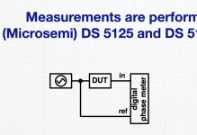
He also describes, as I also suggested previously, how a proper measurement setup is to be done ->
//
So why have you been claiming this all the time - this is my objection.
However the third plot clearly prove that the DAM is source dependent since there is 12-13 dB of phase noise difference betwen the different sources.:yes
But it is good that you also admit this now that you where guessing.
And btw - the link to the Italian professor about jitter uses the definition that jitter is > 10 Hz.
He also describes, as I also suggested previously, how a proper measurement setup is to be done ->
//
Attachments
I'm not guessing nothing, the plot is clear, the noise difference comes from the source.
I repeat again: if the outgoing LRCK was not affected by the source the measured phase noise should be the same regardless of the incoming clock.
It's not so, there is a difference of 12-13 dB, then the added noise is coming from the source and passes the FIFO.
I cannot estimate how much noise comes from the incoming clock, but without any doubt some noise passes through.
I well know how I could measure to discern the input noise, but but it is not of my interest because it does not help to improve a a disastrous oscillator.
So I repeat again, ask the designer to buy a Microsemi 5330A to investigate the issue.
I will spend my time to replace the front end.
No, not if there is intrinsic jitter - thats basic and I cant see how you can overlook that.
//
//
Absolutely yes, otherwise the phase noise should be the same with both sources.
It looks like you don't know what different time domains means.
The FIFO has its own clock, so there is no reasons to measure different phase noise, unless the time domains are mixed up.
That's what happens in the DAM1021.
It looks like you don't know what different time domains means.
The FIFO has its own clock, so there is no reasons to measure different phase noise, unless the time domains are mixed up.
That's what happens in the DAM1021.
You are utterly confusing and confused.
Goodby. Good luck.
//
Not exactly, your electronic skills are very limited, you have to study a bit.
After several days of debating you have not yet understood how different time domains work.
I cannot estimate how much noise comes from the incoming clock, but without any doubt some noise passes through.
I well know how I could measure to discern the input noise, but but it is not of my interest because it does not help to improve a a disastrous oscillator.
As the LRCK is used to transfer the bit state, this is the critical part of all R2R DAC's. Some transition as on PCM63, PCM1704... is done at different stage.
Now as you told some xx days ago, that data & latch clock for the positive and negative part of the R2R is feed & isolated by a C & R circuit.
This means, we have for the C-R latch signal an unknown contribution of switching jitter even a sch-mitt-trigger is involved.
In other words if this is the case 😱 😱 😱 kiss it and say goodby.
An other method would be to measure a pure & clean fs/4 sine (or other freq.) as others do or measure. Most even with AP555b even do not like to zoom in (Page Redirection), in other words how bad the side artifacts/Jitter spurious & PN bell would be. All a question how to setup the Acquisition & FFT& display of.
Hp
This is the DAM1021.
As I have already said, AC coupling is the cheapest solution but not the best way to clock the DAC switches in bipolar configuration.
Indeed in our DACs we use a different approach, but it's also more expensive.
BTW I don't believe it will be dramatic, the long term variations of the coupling capacitors don't affect the conversion.
The investigation to discover the composition of the LRCK phase noise, as I said in a previous post, is a waste of time.
It does not help improving the performance of a poor oscillator and neither helps improving the FIFO isolation.
So I have no interest wasting my little free time on this research.
The only one who should be interested is the designer.
No, not if there is intrinsic jitter - thats basic and I cant see how you can overlook that.
//
Absolutely yes, otherwise the phase noise should be the same with both sources.
It looks like you don't know what different time domains means.
The FIFO has its own clock, so there is no reasons to measure different phase noise, unless the time domains are mixed up.
That's what happens in the DAM1021.
You are utterly confusing and confused.
Goodby. Good luck.
//
Not exactly, your electronic skills are very limited, you have to study a bit.
After several days of debating you have not yet understood how different time domains work.
When one is no longer able to climb mirrors, he is forced to run away and hide.
This is the typical behavior of the fanatic follower.
Tbh as a reader you’ve come off as the one whose wrong, and on top of it rather unpleasant. And then to see a post like this^? Good lord, I don’t care how good your product is I’d hate to support you.
rather unpleasant
quite an understatement 😉
He is very full of himself and he likes to use a lot of bandwidth...
It is a question of points of view, for me it is unpleasant who tries to deny the evidence of the measurements without proper technical knowledge.
Those without proper knowledge should avoid discussing technical matters.
And moreover those who are happy with the DAM can avoid reading this thread, it is not mandatory.
I bought the DAC, paid for it, listened to it and am not at all satisfied with the sound quality.
Therefore I am trying to modify it in order to improve the sound quality, precisely in the spirit of this forum: diy audio.
Mola Mola Tambaqui DAC and Streamer Review | Page 5 | Audio Science Review (ASR) Forum
It seems that the Soekris only has PLL which does not isolate the source clock. The Soekris is missing the ASRC which would totally isolate the source clock. Is my understanding correct?
If people are going to shell out serious moolah for a DAC, least thing you can do is show an objectively provable benefit. Low jitter is also something I like to that's why we ended up coding our own ASRC algorithm.
It seems that the Soekris only has PLL which does not isolate the source clock. The Soekris is missing the ASRC which would totally isolate the source clock. Is my understanding correct?
The DAM1021 has a FIFO buffer but I believe it does not provide good isolation from the source.
And moreover the PLL tracks the incoming clock.
And moreover the PLL tracks the incoming clock.
quite an understatement 😉
He is very full of himself and he likes to use a lot of bandwidth...
I really enjoy his approach, always push the measurements he did, while denying any measurements he didn't do (or knowledge he doesn't understand) on the subjective grounds of "superior sound".
Andrea, as long as you will keep trying to have the cake and eat it too, you will only dig yourself in an ever deeper hole. Good luck, others had already infinite patience with you until they gave up. Something I cannot afford to do, unfortunately. As I said many times, while I have lots of tolerance with the subjective camp, trusting their ears over anything else, I have zero tolerance for those trying to justify their subjectivity by inventing their own version of physics.
Is my understanding correct?
No. The last thing the DAM needs is an ASRC. A good clock with a good reclocking scheme is all that's needed as far as i am concerned.
I really enjoy his approach, always push the measurements he did, while denying any measurements he didn't do (or knowledge he doesn't understand) on the subjective grounds of "superior sound".
Andrea, as long as you will keep trying to have the cake and eat it too, you will only dig yourself in an ever deeper hole. Good luck, others had already infinite patience with you until they gave up. Something I cannot afford to do, unfortunately. As I said many times, while I have lots of tolerance with the subjective camp, trusting their ears over anything else, I have zero tolerance for those trying to justify their subjectivity by inventing their own version of physics.
Dear synapses08,
what is the reason I should care about your "tolerance"?
I have just measured the impact of you "tolerance" on my audio design approach: the result was below the noise floor of the instrument.
If it was not clear I care less than zero even about you measurements and your opinion.
If you think I care about your opinion, you are very presumptuous.
But sorry, I don't care about your opinion.
BTW, we have built some oscillators, we have measured them with the Timepod 5330A in 3 cornered hat mode with cross correlation.
The right instrument and the best way to measure an oscillator.
The measurements told they are very good oscillators, in class of the best oscillators on the market.
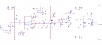
Then I found the circuit in the attached picture.
I have no words.
Attachments
Dear synapses08,
what is the reason I should care about your "tolerance"?
There is no reason, you should not. The fact you are speechless ("no words") is a good thing.
There is no reason, you should not. The fact you are speechless ("no words") is a good thing.
In fact, when I saw your circuit I was speechless.
What a masterpiece of engineering!
Your contribution to the audio community is immeasurable.
By comparison, the SCP-2 is a beginner's toy.
- Home
- Source & Line
- Digital Line Level
- Implementing a true FIFO buffer with low phase noise clock on the Soekris DAM1021 DAC