I must say this is one of the best threads I have read in DIYAudio for a long time. Can't say I understand all of it but still an excellent read, even if I can understand 1/2 of it, it is still enlightening 🙂
Big thanks to JohnW's participation and xx3stksm for getting it going, cheers to all. Rick
Big thanks to JohnW's participation and xx3stksm for getting it going, cheers to all. Rick
I must say this is one of the best threads I have read in DIYAudio for a long time. Can't say I understand all of it but still an excellent read, even if I can understand 1/2 of it, it is still enlightening 🙂
Big thanks to JohnW's participation and xx3stksm for getting it going, cheers to all. Rick
Yes, for me too.
thnaks to all
Looking at the stuff people use in this thread, they're really non-standard stuff. Either fpga and solid, or too small to hand solder (for most), or different logic family/voltage levels etc.
This topic of what flip flop to pick has gone on and on in the DSC1 thread (or another one?), best you ask thereI'm afraid.
Last but not least: iirc the DSC1's usually use the HCT family, supposedly for lower distortion or other reasons, which seem to be hard to get.
Good luck Zoran!
I am sorry for asking a trivial question. 🙁
.
I just want to have opinion from people with more knowlege and personal experience (like You for the example).
I asked for the single flip-flop (or dual flip flop recommendation), not for the already made in circuit shift regsters (like 594, 595, 164 etc).
.
anyway thanks
Sory but I did not notice that You are using the fpga-s and so in Your designs. And noone directed You into diferent topic? I am sure that You are able to solder this parts. (I can solder small ic-s)Looking at the stuff people use in this thread, they're really non-standard stuff. Either fpga and solid, or too small to hand solder (for most),
Cheers and I like Your designs published here on diy. 🙂
Sory but I did not notice that You are using the fpga-s and so in Your designs. And noone directed You into diferent topic? I am sure that You are able to solder this parts. (I can solder small ic-s)
Cheers and I like Your designs published here on diy. 🙂
Hi Zoran,
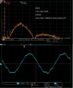
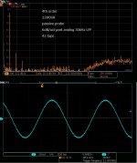
I am currently using a CML flip flop from Analog Devices, the HMC723. To me it's just to see what an (virtually) ideal single bit Flip Flop is capable of (and to see what the pro's and cons are compared to CMOS etc).
It is solderable by hand, but has a non-standard foot, as well as needs a negative voltage for it's power supply, so interfacing is not as easy as normally is the case. Feeding it with wrong signal levels will break the chip easily. It's also expensive, at about €75.- per FF, non-ceramic version and of course you need 2 for stereo.
Product page on Mouser:
Analog Devices Inc. HMC723 Series Flip Flops | Mouser
You could make this e.g. into a 4 bit balanced FIR with the help of a clock distributor ic like the HMC940, but that might be a "bit" too much ;-)
Not having spare time on my hands and using prototyping boards my last results can be seen on the screendump, optimized for maximum level, with matching higher 3rd harmonic. This can be bettered easily. Best PM me if you have further questions about these.
Attachments
As long as you are in the digital domain, the principle is true. But our goal is DA conversion, which means the output is always in the analog domain. DAC topology often results in different phenomena in the analog domain. High OSR can sometimes have low distortion and vice versa. There is no concrete principle in the analog domain because DAC topology dominates the situation.
Great read, thanks for that.
Yes I agree the DAC topology dictates the performance.
I'm not really sure if you couldn't apply 1 dB more gain (spdif in or in fpga) since that might better suit the whole analog FIR. After all you might look at that as a pretty efficient integrator)?
Oke long shot (I'm sure you tried all sorts of things):
Did you change the value of the Drain resistors when you added more taps linearly (double taps / half the r value) or did you also experiment after adding taps (assuming you went from 1 tap, chose best power supply levels, current and resistor value). If not, there might be some dB's hidden there.
Ready for a "I did this and more" ;-)
the 2nd season PCB
Thank you for your appreciation. 🙂I have almost finished debugging the 2nd PCB(the 1st pic). The 1st one had 24 taps. I was a little bit skeptical 1bitDSM configured by discrete components could outperform my previous DIYed multibit DSM(3bitDSM). But the 1st one was far better than I expected. The successful result forced me to design the 2nd PCB since manufacturing PCB is way easier than before as long as you have CAD to make Gerber files.
It took about two months to debug the 2nd PCB. The result is a 50% success. 😱I failed to have the correct IO pads assignment of FPGA for large taps(48 or 36). As long as you are in the digital domain, FPGA has almost no limitation in assigning IO pads. But in my case, unknown restriction, which is revealed only in the actual routing phase, prevented me from full usage. The available tap was 36 out of 48 and 24 out of 36. 12 out of 48 was in a not ideal situation, where additional tap doesn't always mean performance improvement. I have found a way to solve the problem after trial and error. I hope the 3rd season is the final one.
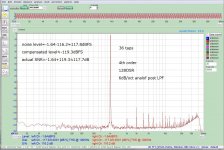
The 2nd pic is an elementary unit, one tap. If you want to measure more than 120dB SNR, I'm sure you need some compensation to cancel the residual noise of your ADC unless you have an expensive one like AP. My ADC(two AD7960s) has almost -123dBFS residual noise. If your DUT is also -123dBFS, what you can have is the square root of the sum: -120dBFS. If DUT is -129dBFS, -122dBFS. It's a rough estimation, but practical. One tap roughly has -129dBFS, which is almost the best number in low noise op-amp application. In other words, One tap has no DSM related degradation. If you can have an ideal analog FIR circuit, the best SNR is 129dB. Of course, it's impossible in the analog domain: imaginary number.
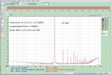
The 3rd pic is in 36 taps, where analog FIR is almost ideal. Compensated SNR(117.7dB) is pretty good since this is done by discrete components. You should compensate THD with a notch filter if you want a more correct number. I'm not a THD person. The compensation is only for SNR: an SNR person.
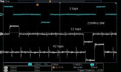
The 4th pic is in 42taps, where 6 out of 42 is not ideal. I intentionally selected six taps to have a better result in SNR but not in THD. I guess the unideal tap can't have a win-win between SNR and THD. If your taps are in ideal condition, they are not a trade-off in 1bitDSM. The better the SNR, the better THD. I'm sure the 3rd version PCB can have 48 ideal taps. I hope a win-win up to 48taps.
The 5th pic is a waveform across the collector(no LPF included). Glitch is the consequence of analog FIR. The lower, the better. 12 taps is pretty good, while 42taps isn't so because of unideal taps. if you could have a better phase relation between taps like in 12taps, it's promising to have 120dB SNR.
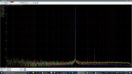
Another advantage of analog FIR with large tap is low out of band noise. The 6th is SACD, where considerable residual noise exists though they are beyond the audio band. The 7th is 42 taps analog FIR. FIR in the analog domain can considerably eliminate the residual noise. Analog post LPF is gentle 6dB/oct only. My 3rd PCB is next year. I hope it blooms in next April like a cherry blossom.
I must say this is one of the best threads I have read in DIYAudio for a long time. Can't say I understand all of it but still an excellent read, even if I can understand 1/2 of it, it is still enlightening 🙂
Big thanks to JohnW's participation and xx3stksm for getting it going, cheers to all. Rick
Thank you for your appreciation. 🙂I have almost finished debugging the 2nd PCB(the 1st pic). The 1st one had 24 taps. I was a little bit skeptical 1bitDSM configured by discrete components could outperform my previous DIYed multibit DSM(3bitDSM). But the 1st one was far better than I expected. The successful result forced me to design the 2nd PCB since manufacturing PCB is way easier than before as long as you have CAD to make Gerber files.
It took about two months to debug the 2nd PCB. The result is a 50% success. 😱I failed to have the correct IO pads assignment of FPGA for large taps(48 or 36). As long as you are in the digital domain, FPGA has almost no limitation in assigning IO pads. But in my case, unknown restriction, which is revealed only in the actual routing phase, prevented me from full usage. The available tap was 36 out of 48 and 24 out of 36. 12 out of 48 was in a not ideal situation, where additional tap doesn't always mean performance improvement. I have found a way to solve the problem after trial and error. I hope the 3rd season is the final one.
The 2nd pic is an elementary unit, one tap. If you want to measure more than 120dB SNR, I'm sure you need some compensation to cancel the residual noise of your ADC unless you have an expensive one like AP. My ADC(two AD7960s) has almost -123dBFS residual noise. If your DUT is also -123dBFS, what you can have is the square root of the sum: -120dBFS. If DUT is -129dBFS, -122dBFS. It's a rough estimation, but practical. One tap roughly has -129dBFS, which is almost the best number in low noise op-amp application. In other words, One tap has no DSM related degradation. If you can have an ideal analog FIR circuit, the best SNR is 129dB. Of course, it's impossible in the analog domain: imaginary number.
The 3rd pic is in 36 taps, where analog FIR is almost ideal. Compensated SNR(117.7dB) is pretty good since this is done by discrete components. You should compensate THD with a notch filter if you want a more correct number. I'm not a THD person. The compensation is only for SNR: an SNR person.
The 4th pic is in 42taps, where 6 out of 42 is not ideal. I intentionally selected six taps to have a better result in SNR but not in THD. I guess the unideal tap can't have a win-win between SNR and THD. If your taps are in ideal condition, they are not a trade-off in 1bitDSM. The better the SNR, the better THD. I'm sure the 3rd version PCB can have 48 ideal taps. I hope a win-win up to 48taps.
The 5th pic is a waveform across the collector(no LPF included). Glitch is the consequence of analog FIR. The lower, the better. 12 taps is pretty good, while 42taps isn't so because of unideal taps. if you could have a better phase relation between taps like in 12taps, it's promising to have 120dB SNR.
Another advantage of analog FIR with large tap is low out of band noise. The 6th is SACD, where considerable residual noise exists though they are beyond the audio band. The 7th is 42 taps analog FIR. FIR in the analog domain can considerably eliminate the residual noise. Analog post LPF is gentle 6dB/oct only. My 3rd PCB is next year. I hope it blooms in next April like a cherry blossom.
Attachments


Great read, thanks for that.
Yes I agree the DAC topology dictates the performance.
I'm not really sure if you couldn't apply 1 dB more gain (spdif in or in fpga) since that might better suit the whole analog FIR. After all you might look at that as a pretty efficient integrator)?
Oke long shot (I'm sure you tried all sorts of things):
Did you change the value of the Drain resistors when you added more taps linearly (double taps / half the r value) or did you also experiment after adding taps (assuming you went from 1 tap, chose best power supply levels, current and resistor value). If not, there might be some dB's hidden there.
Ready for a "I did this and more" ;-)
The last pic(the 5th) is OSR vs. frequency response in the digital domain.
PCM-DSD_Converter | PCMDSD.com - Converting PCM to DSD.
This is a comparison between PCM to DSD converter. The 4th has HPplayer (ASDM7).
serieril(せりえりる) on Twitter: "PCM-DSD変換性能比較。SONY DSD Direct、KORG AudioGate 4、Wave to Dsdiff Converter、JRMC、SoX-DSD、XLD、Foobar2000(TypeD)、TASCAM Hi-Res Editor、Weiss Saracon、SONAR、HQPlayer、そして拙作PCM-DSD_Converterを32bit/64bitFloat精度に大まかに分けた。… https://t.co/4I1x6mJmtk"
Yes, "I did this and more." 😀The collector(drain) resistor, the emitter, the base, the switching voltage amplitude, the collector current, the collector voltage, and the transistor(BFR360) can change the performance. It's impossible to find the best combination because they are connected together; they are not independent in the analog domain. But I'm still struggling to find a better solution. It's straightforward to have the best combination in the digital domain; they are independent.
Edit: The 1st HP probably includes the 2nd.
Last edited:
Thanks for the answers but I still can't fathom it's method of working - my main stumbling block being the negative phase output from one DAC? Sorry if I'm being stubbornly stupid.
But I found this Tektronix PDF (interleaved DACs in AWG a bit further) which explains in Fig 13 that the input signal is 1/2 clock delayed & phase shifted to the DAC which also runs on a delayed clock http://www.tek.com/dl/76W_29216_0_MR_Letter.pdf
No expert and having trouble wrapping my head around this, I can make some observations:
What seems to be off here is that they already achieve 25GS/s with a single DAC chip running at a 12.5GS/s clock. It looks as if the single, basic DAC already consists of 2 FF`s that are positively edge clocked at 12.5 GHz, one with an inverted clock phase w.r.t. the other, presumably using RTZ encoding and fed with 25 GS/s data.
The non-interleaved data flow isn`t described, so this is all just a wild guess on my part.
I don`t think you should read into this too much, as they`re clearly leaving out important details.
Always another question though 🙂 - is this not the same as delaying by 1/2 clock, the neg phase analog output of a differential output DAC?
It seems to be, but I found in examples that the input for the interleaved dac chip is inverted, at the output this is corrected by adding the positive output to the normal dac`s section negative output. Can`t make heads or tails though.
Why isn't this a commonly used approach in DACs? As there ar eother stated advantages besides increased bandwidth according to Tek:
The interleaved structure has many drawbacks for audio. E.g. one of the things that can happen when things aren`t tightly matched is distortion products being generated in the lower frequency (audio) band.
Also, the whole idea that 1 bit conversion is inherently linear now needs all sorts of calibration and adjustments to work right (expensive), all for the sake of bandwidth of which there`s already plenty of.
It`s a technique for very high sample rates and those aren`t concerned at all about resolution above e.g. 12 bits.
This is a nice paper wrt drawbacks etc:
https://research.utwente.nl/files/6419610/Olieman_IEEE_JSSC_March_2015.pdf
In short: purely suited for extreme high frequencies and relative low resolution.
Caps where only mounted for photo 🙂 , the array on this design operates at 4.5V as the design is USB powered and we struggle with the 500mA USB current limit, although we will still be a little over......
The larger Array design operates at upto 6V1...
Keen for the results ASAP 🙂
4.5 volts after regulation, right? Best to also deliver a good USB cable (low resistance power supply leads) with the dac I guess.
Any results come in yet, or something popped up?
when can I buy this DAC? 😀
It's a difficult question because my DIY is a particular design for my circumstance.😱 My system is a 4-way multi. My DAC has two channels but doesn't mean L and R but low and middles or high. That's the reason I have 48 taps(middle or high) and 36 taps(low). The input is particular too. The input signal, which is fed by transport, is an optical interface for isolation from the earth ground. IIS is easy to implement, but the frequency is 96kHz only because my transport has SSRC that converts every file into 96kHz/24bit. My motivation for DIY is to design a unique DAC since I can't find the best one for my system out there. There is little chance to make a universal one.
Hi Zoran,
I am currently using a CML flip flop from Analog Devices, the HMC723. To me it's just to see what an (virtually) ideal single bit Flip Flop is capable of (and to see what the pro's and cons are compared to CMOS etc).
It is solderable by hand, but has a non-standard foot, as well as needs a negative voltage for it's power supply, so interfacing is not as easy as normally is the case. Feeding it with wrong signal levels will break the chip easily. It's also expensive, at about €75.- per FF, non-ceramic version and of course you need 2 for stereo.
Product page on Mouser:
Analog Devices Inc. HMC723 Series Flip Flops | Mouser
You could make this e.g. into a 4 bit balanced FIR with the help of a clock distributor ic like the HMC940, but that might be a "bit" too much ;-)
Not having spare time on my hands and using prototyping boards my last results can be seen on the screendump, optimized for maximum level, with matching higher 3rd harmonic. This can be bettered easily. Best PM me if you have further questions about these.
Hi Thanks For the answer.
(I am afraid that this part is not for my purposes, I need 32bit serial to parallel bit...)
The PCM4202 are still the best sounding ADC's we are aware of that have a true 1bit SDM output (not a faked 1bit output re-modulated / decimated from a multibit SDM).
The trouble with the PCM4202's is that they have a 'high' NF at about -140 to -145dB... perfectly adequate for Audio, but not for measurement...
We will have a look at the AD part for a test system, we have been planning for a long time now to update the UPD's internal ADC board.
What about AKM5578 is seems much better than PCM4202?
The "DSD" outputs of the AKM5578 are not native DSD, they are re-modulated from the native mutlibit Delta sigma architecture..
The PCM4202 has native DSD outputs and IMO audibly Superior in DSD mode...
The PCM4202 has native DSD outputs and IMO audibly Superior in DSD mode...
The "DSD" outputs of the AKM5578 are not native DSD, they are re-modulated from the native mutlibit Delta sigma architecture..
The PCM4202 has native DSD outputs and IMO audibly Superior in DSD mode...
I see but native or not AKM5578 has much better THD+N, SNR and also suppor dsd256. How do youm decided PCM4202 is a better sounding ADC?
Sub 0.01%THD and SNR has ZERO refection on sound quality!!! Designing by "Simplistic" numbers is a fools game!
We design products with both devices, the PCM4202 wins hands down in DSD mode - we only use the AKM for Test and measurement applications where highest measured performance is required...
The PCM4202 SDM to PCM decimating filters are not the best sounding, the PCM4202 should only be consider for pure DSD mode or where external decimation filters are used.
Native unmolested DSD is so sonically Superior to PCM its hard to understand why there is still any argument - I can only presume that people have not heard true native DSD verses PCM Mastered from the same source material.
Sub 0.01%THD and SNR has ZERO refection on sound quality!!! Designing by "Simplistic" numbers is a fools game!
We design products with both devices, the PCM4202 wins hands down in DSD mode - we only use the AKM for Test and measurement applications where highest measured performance is required...
The PCM4202 SDM to PCM decimating filters are not the best sounding, the PCM4202 should only be consider for pure DSD mode or where external decimation filters are used.
Native unmolested DSD is so sonically Superior to PCM its hard to understand why there is still any argument - I can only presume that people have not heard true native DSD verses PCM Mastered from the same source material.
I see thanks, did you know any FPGA solution have better DSD (PDM) modulation?
- Home
- Source & Line
- Digital Line Level
- My no DAC project, FPGA and transistors