To be honest I thought slightly different:
not only the PCB, but the ES9038 soldered and maybe the controller a base clock.
something like that just definitely not for this price
")
1pair MP-D2 MK2 ES9038PRO DAC decoder Module 932267335970 | eBay
Although it can be considered to buy a good PCB and the chip itself and put everything around it on the highest level we discussed here - although this way is more risky.
@Mark it maybe a stupid question, but how complicated the microcontroller stuff is? Would it be possible to do it from scratch? Or is it an extremely big work? and better to buy the complete board.
how complicated the microcontroller stuff is? Would it be possible to do it from scratch? Or is it an extremely big work? and better to buy the complete board.
Wonder if you realize you posted a link to a document about the same as what I have. That is against the rules here by the way, so you might want to be careful to stay out of trouble. But since you have seen it you must be able to see what it says, and what it says is what you would need to know to answer your own question about how complicated it would be.
Also, if you have been reading the thread carefully, some of the microcontroller code has already been captured with a logic analyzer and posted here. By the way, something like this is good enough for I2C capture and analysis: New USB Logic Analyzer Device Set USB Cable 24MHz 8CH 24MHz for ARM FPGA M100 7000000492822 | eBay Between seeing the code running on the microcontroller and reading the information you already have you should be able to figure out how it works, and how hard it would be to DIY.
I don't understand your question about buying the complete board.
Last edited:
This is not a review and there is not much mod. Just the first impression of an inexpensive DAC using the ES9038Q2M.I finally received my ES9028Q2M box from MSHOW Audio Shop in China. It does not include a power supply. I pressed the 12V/3A power brick from the Topping VX1 power amp into service. I just watched HULU movie for the last half hour. It is quiet and has good sound stage. The 120 dB volume control is very nice. But the Apple Remote does not work yet. I will try pairing tomorrow.
ES9038 ES9038Q2M DAC Decoder board Support IIS DSD DOP 384KHz with Amanero USB | eBay
The DAC links the TV cable box and a Sony BDP-7200 Blu-Ray player to a Harman Kardon AP2500 preamplifier. The Blu-Ray player also serves as my CD player.


The DAC is built around the VR1.07 of the ES9038Q2M board we discuss on this thread. At the beginning, I used a switching PS from the Topping VX-1. It sounds very good from the get go. The sound is open and transparent. It has a stable sound stage with good depth. The construction of the DAC box is well executed. A lot of hot glue to hold down the TFT display panel and wires. I like the upgraded RCA socket, better than the one on the original board.


I built a linear power supply for it. It can output 9 to 15 volts up to 1 ampere. It has a good size toroidal transformer and the board has a DC voltage panel for easy setting.

I was planning to install a dual voltage PS. But there is not enough room inside to house the transformer and PS board. I went the easy route.
I did not even try to add I/V. I just replace the output stage opamp with a LME89720. The board came with NE5532DD which should be very good. I changed the opamp only because I have a whole bunch of the 720 in my spare box.


I purchase an Apple Remote which allows me to perform all the front panel functions.

My previous DAC were a Rotel RSP-1570 (for main audio) and a Tianyun Zero DAC (computer sound). Both were 10 years old vintage. It is not surprising that the MShow DAC sounds pretty decent to me. The TFT display and remote function are nice bonus. I will not hesitate to recommend this as good investment for the money, at half the price of name brand DAC. In fact, later this month, I will try to sell mine to finance my ES9028PRO project.
Last edited:
abraxalito, as you have the simulation tool running, could you please check what would be adequate resistor values for this circuit in case of an LME49720 opamp?
Would be also interesting to see your simulation circuit in LTSpice to make my own simulations (I did just discover Spice last week-end, but not sure how to simulate this circuit correctly..)
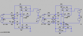
Hi freezebox - here's my suggested replacement, alongside the original. If you need the .asc file rather than just a screen grab, let me know. I've scaled the impedances to be roughly the same load on the I/V opamps at low frequencies, and aimed at 2k.
Attachments
What do you mean by undue loading? Current limiting on the peaks?
I mean loading beyond the manufacturer's provided data. For opamps that provide THD+N plots, the load impedance is typically 2k, sometimes 10k and/or 600ohms. The 600ohms case is in general poorer than with higher impedances. This can be seen in the applications information for the AD797 for example.
With the LM4562 - and this seems to me to be a unique case - the +ve rail PSRR is shown with differing loads. The 600ohm load shows about 10dB poorer figures at HF than higher impedance loads.
Current limits for opamps aren't the same as the maximum linear output current. On ADA4898 for instance the linear output current (high voltage rails) is 40mA whereas the current limit is 150mA, approx 1:4 ratio. If this ratio can be assumed to work for the NE5534 then the linear output current would be around 10mA since its limit is 38mA. With a 600ohm load 10mA gives us a 6V peak swing - I'd be interested to see the THD+N plot for a 5534 @ 20kHz with a 600ohm load vs with a 240ohm load.
Only thing I can think that could have some mitigating effect would be that the IV opamps outputs only swing +-1v p_p. They aren't working very hard at that output voltage and they don't need to supply a lot of current into low Z loads if the voltage never goes higher than 1v. May I ask if you have been modeling IV opamp distortion for the <= 1v output operating condition?
I gave up modelling I/V opamp distortion many years ago, when I couldn't find any correlation between what I heard and what the sim was doing. I suspect now that the reason was quite simple - subjectively power supplies make a substantial difference but opamp models don't handle power supply current draw correctly. I think Kendall Castor-Perry looked into this at great length in a series of articles.
Previously you said, "In the second, the input impedance of the bal-SE stage is too low .."
Then you said, "I just put the schematic into LTSpice which confirmed my suspicions - that those particular resistor choices place undue loading on both the I/V opamps..."
So, what I am trying to understand is what did you do in LTSpice to confirm you suspicions that the there is undo loading on the IV opamps?
The reason I am trying to understand that is because the IV opamp outputs only swing +-1v p_p, which means the output current is 10 times less than if they were going +-10v.
So, however you determined that the loading was too much using LTSpice, did you take into account any effects of the small output voltage and thus small output current under actual operating conditions? Does that make sense what I am asking about?
The discussion over the ADA4898 has indicated to me that the aim here isn't to get the best sounding design. Rather to get the best measuring design with the best possible sound.
Read my post
Previously you said, "In the second, the input impedance of the bal-SE stage is too low .."
Then you said, "I just put the schematic into LTSpice which confirmed my suspicions - that those particular resistor choices place undue loading on both the I/V opamps..."
So, what I am trying to understand is what did you do in LTSpice to confirm you suspicions that the there is undo loading on the IV opamps?
I ran the sim and asked it to show me what the input currents were to both + and - sides. The reason I couldn't tell this directly by observation is the 470ohm resistor's far side is 'bootstrapped' by the opamp and so gives a lower impedance than merely a passive 470ohm load.
The reason I am trying to understand that is because the IV opamp outputs only swing +-1v p_p, which means the output current is 10 times less than if they were going +-10v.
Sure, I accept your point about current but I don't see characterization in any audio opamp datasheet for what happens with loads below 600ohm. Distortion is specified with example load resistances, not with a current source as load.
In the circuit I analyzed the I/V opamp feedback resistance is 2k72 so would you confirm that the peak output current from the DAC is 368uA? (This seems rather low for any DAC which is why I'd like confirmation).
So, however you determined that the loading was too much using LTSpice, did you take into account any effects of the small output voltage and thus small output current under actual operating conditions?
No I didn't because I'd have to guess, uneducatedly to what degree the issue was mitigated by the relatively small output swing.
Going back to my earlier mention of the PSRR plot for the LM4562 - this is a measurement presumably made with negligible current flowing in the output load resistor, yet there's clearly about 10dB degradation in PSRR with 600ohm load compared to 2kohm. Given I'm more concerned with PSRR than I am with THD+N for me there can't be a good reason for wanting such a low load impedance when the price for it is 10dB poorer PSRR.
Read my post
Yeah I did and even opened up the ADA4898 DS and pondered your points. I feel you could have been more persuasive than you were as to the technical merits of that part.
First up, the OL gain/phase plot cuts off at 100kHz so we can't directly read off the loop gain for 20kHz, but we can make a reasonably educated guess at what it is from the CMRR and PSRR plots, plus the mention in the blurb that the OL gain is in excess of 100dB. All this additional stuff tells us its not one of those video type opamps where the OL gain corner is set fairly high, rather the OL gain looks to have a corner in the area of 200Hz (give or take a bit). So it would be reasonable to extrapolate from the 100kHz THD figure to the 20kHz one with a 14dB reduction. I reckon.
Thanks for the vote of confidenceYeah I did and even opened up the ADA4898 DS and pondered your points. I feel you could have been more persuasive than you were as to the technical merits of that part.
unlike many here I actually have limited time to spend at DIYA - there is real work to be done. ATM trying to repair aLexicon 224XL.... no trivial task.... then 'brain' of a Digico Console... then some actual fun, a Dumble ODS.
First up, the OL gain/phase plot cuts off at 100kHz so we can't directly read off the loop gain for 20kHz, but we can make a reasonably educated guess at what it is from the CMRR and PSRR plots, plus the mention in the blurb that the OL gain is in excess of 100dB.
I assumed Mark would know all that stuff, he seems pretty switched on. The CM distortion is something not many people consider as is the stuff about
harmonic weighting / cancellation. No time for an opamp theory lesson and
he doesn't need it.... I think!
All this additional stuff tells us its not one of those video type opamps where the OL gain corner is set fairly high, rather the OL gain looks to have a corner in the area of 200Hz (give or take a bit). So it would be reasonable to extrapolate from the 100kHz THD figure to the 20kHz one with a 14dB reduction. I reckon.
Prolly... sounds close to the mark ..... I'm sure you've read the Groner paper on opamp distortion and even some rubbish opamps perform amazingly well in inverting mode.
Agreed - The ADA4898 cut's a nice middle ground between 'slower' very high OLG 'audio' opamps and 'super fast' low OLG CFB opamps.
I took the time to read and try to comprehend the articles and it was very informative. Thanks for the reference to that work.I gave up modelling I/V opamp distortion many years ago, when I couldn't find any correlation between what I heard and what the sim was doing. I suspect now that the reason was quite simple - subjectively power supplies make a substantial difference but opamp models don't handle power supply current draw correctly. I think Kendall Castor-Perry looked into this at great length in a series of articles.
To save anyone else the google-fu for KC-P's work, here's a link to get you started : https://www.edn.com/design/power-management/4412969/Why-bypass-caps-make-a-difference---Part-3--Op-amps-and-supply-variation
To be honest I thought slightly different:
not only the PCB, but the ES9038 soldered and maybe the controller a base clock.
.....
actually you are asking for a TP buffalo board. that is a slightly different approach than we are discussing here.
Why does anyone suppose ADA4898 DS omits data below 100kHz? Isn't that kind of unusual for a device that would be expected to useful down there? I know one can extrapolate and so on, but the missing data looks like more of a red flag to me. If it is a good audio part then what was the marketing department thinking?
Anyway, if one actually gets built into a DAC mod I guess we will find out one way or another. I am curious about what will happen of course, but I sure don't want to do the work myself to find out since I'm not expecting much. Glad you two seem to be volunteering though. Hope you will do listening tests to A/B compare it with LME497xx?
Anyway, if one actually gets built into a DAC mod I guess we will find out one way or another. I am curious about what will happen of course, but I sure don't want to do the work myself to find out since I'm not expecting much. Glad you two seem to be volunteering though. Hope you will do listening tests to A/B compare it with LME497xx?
Anyway, if one actually gets built into a DAC mod I guess we will find out one way or another. I am curious about what will happen of course, but I sure don't want to do the work myself to find out since I'm not expecting much. Glad you two seem to be volunteering though. Hope you will do listening tests to A/B compare it with LME497xx?
I'm unclear what in what myself or Terry (@zenelectro) has written that has led you to surmise we're volunteering. I long ago left behind using opamps in my DAC output stages (I tried a few that lack AF THD characterisation like AD603, AD605 & AD8129/30 with acceptable results), I found they all were limited in their subjective results by their power supplies so I went over to purpose-designed discrete circuits with a focus on achieving the best possible PSRR.
I can't speak for @zenelectro though.
Incidentally if anyone's curious to see what one of my DAC I/V stages looks like I recently shared a pic on the 'DAC gallery' : DAC gallery
Last edited:
All this talk of op amps in output stages has me confused...
I thought op amps were best avoided in output stages, hence the best sounding designs either use transistors (e.g. Fetishizator, Marantz HDAM) or tubes (e.g. Lampizator).
Hi freezebox - here's my suggested replacement, alongside the original. If you need the .asc file rather than just a screen grab, let me know. I've scaled the impedances to be roughly the same load on the I/V opamps at low frequencies, and aimed at 2k.
Thank you very much! I will try to re-built it in LTSpice as lessons learned. The opamp you were using is similar to LM49720? As I understand, Zin is deviating from opamp to opamp though it might not easily be exchanged by another one, right?
Sorry, but the discussion about opamps and swinging exceeds by far my knowledge about EE - I am a mechanical engineer that Need to see components moving to be able to imagine how things work.. but I will try my best.. ;-)
It is a pitty you come along with your findings in this thread at this late timing, as I have already built my opamp i/v stage. So far I am quite happy with it (except the high opamp temp. when running) thanks to the advises from Mark, but improvements are always welcome. If we listen to the sonic experience reports of cdgames building the Katana DAC with descrete opamps there must be something with it and just explaining everything with a higher H2 distortion is not a satisfying statement to me as the measurements of Katana show very low distortion as well. Anyway I don´t know who ever did some Audio distortion check (e.g. on Klippel Homepage) to really see the impact on sound that distortion has when added to a Music signal. Talking about -100 dB and less is not audible (at least not to me). But what I hear are differences between DAC´s with the mods I did, so something else has to be taken into account here I guess.
Thank you very much! I will try to re-built it in LTSpice as lessons learned. The opamp you were using is similar to LM49720? As I understand, Zin is deviating from opamp to opamp though it might not easily be exchanged by another one, right?
Zin here is determined by the choice of passive components (Rs and Cs) not the opamp. LME49720 is the same as LM4562 as I understand it, that should work very well in this circuit, measurement-wise.
Talking about -100 dB and less is not audible (at least not to me). But what I hear are differences between DAC´s with the mods I did, so something else has to be taken into account here I guess.
I would agree, even -60dB of 2nd harmonic isn't likely to be audible. So I very much doubt that the audible differences between DACs are down to distortion performance, in my view we'd be better off finding a consistent way to measure noise modulation to get closer to understanding audible differences.
- Home
- Source & Line
- Digital Line Level
- ES9038Q2M Board