Damn, you right 🙂
I use flat top windows, with hann this low frequency effect just disappear...

Thanks 🙂
I use flat top windows, with hann this low frequency effect just disappear...
Thanks 🙂
Indeed the windowing is a key for good measure, example with a 40Hz signal:

Above a flat top window

above a hann

and a blackman harris
Above a flat top window
above a hann
and a blackman harris
Hello,
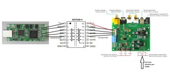
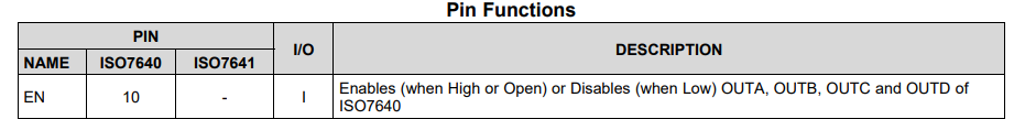
I have chinese clone es9038q2m board and xmos xu208+cpld from Lusya store in aliexp. When i use isolator ISO7640FM to i2s lines and start play, the lock LED on dac turns off, otherwise it remains on. After isolation, is reclocking needed or not?
I have chinese clone es9038q2m board and xmos xu208+cpld from Lusya store in aliexp. When i use isolator ISO7640FM to i2s lines and start play, the lock LED on dac turns off, otherwise it remains on. After isolation, is reclocking needed or not?
Do you have a scope and a DVM? Is the isolator powered correctly on both sides of the isolation barrier?
Reclocking might help once you get the dac working at all with the isolator. There are usually a lot of things that could use fixing with Chinese dac boards, and or Amanero clones. If you can provide links to what you bought, and pics of how you have things hooked up now, it would help to understand the details of your setup better. In that case would probably give you more and better advice than we could at this point.
Regarding reclocking and other details of dac system design, you might check out the thread at: https://www.diyaudio.com/community/threads/general-purpose-dac-clock-board.413001/
Reclocking is useless in this case. Does it work without isolator?I have chinese clone es9038q2m board and xmos xu208+cpld from Lusya store in aliexp. When i use isolator ISO7640FM to i2s lines and start play, the lock LED on dac turns off, otherwise it remains on. After isolation, is reclocking needed or not?
Hi all!
Yes, it works fine without isolator, I made a sketch of the wiring, pin10 is open.
Yes, it works fine without isolator, I made a sketch of the wiring, pin10 is open.
Attachments
Last edited:
The wiring seems to be ok. Isolator outputs can have high overshoot so series termination resistors are typically needed on output side. Do you have a scope?
It may be that the DPLL cannot lock with the I2S signals from the isolator. There is a register setting (register 12) for DPLL bandwidth but that would require major modifications (bypassing MCU and using external MCU for I2C).
You should connect 2-8 and 9-15 pins. I saw on the data sheetHi all!
Yes, it works fine without isolator, I made a sketch of the wiring, pin10 is open.
Last edited:
I saw @Markw4 dropbox link for arduino programmer, but no files in there. Is there another link for mcu mod?It may be that the DPLL cannot lock with the I2S signals from the isolator. There is a register setting (register 12) for DPLL bandwidth but that would require major modifications (bypassing MCU and using external MCU for I2C).
@Deenoo Hi! Pin 2-8 connected to i2s gnd and 9-15 to dac gnd on the final pcb.
Last edited:
Not sure what your goals are but a separate USB isolator would probably be sufficient. The benefits of I2S isolation are quite slim as that ES9038Q2M board has a non-isolated MCU which also causes noise.
Hello,
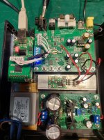
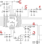
I connected the clean side Vcc of the isolator to 3.3V which comes from the original 3V reg and series 22ohm to bclk, lrck, data pins, installed a separated psu with LT3045 for Avcc pins. It seems good I will not modify anything else, the cost would be the same as if I bought a better built dac.
I connected the clean side Vcc of the isolator to 3.3V which comes from the original 3V reg and series 22ohm to bclk, lrck, data pins, installed a separated psu with LT3045 for Avcc pins. It seems good I will not modify anything else, the cost would be the same as if I bought a better built dac.
Attachments

Does anyone have the AVCC power supply pdf recommended by the manufacturer? The previously published application note link is no longer available.
I installed 2xTPS7A20 with 150ohm load for AVCC, 1x TPS for VCCA both pins, 1x TPS to DVCC, 1x TPS for clock and 1x for isolator clean side Vcc. The controller and toslink remained on the original AMS 3V3. The 6 LDOs get their 5V from onboard utc7805. Main power supply: Denoiser 12V. The sound really improved a lot with 3V3 separation. OPA: LME49860NA I think it is more detailed than with OPA1612.
I installed 2xTPS7A20 with 150ohm load for AVCC, 1x TPS for VCCA both pins, 1x TPS to DVCC, 1x TPS for clock and 1x for isolator clean side Vcc. The controller and toslink remained on the original AMS 3V3. The 6 LDOs get their 5V from onboard utc7805. Main power supply: Denoiser 12V. The sound really improved a lot with 3V3 separation. OPA: LME49860NA I think it is more detailed than with OPA1612.
Hi, am looking to learn a bit more about the es9039 dac and am thinking of this board
https://www.aliexpress.com/item/1005007308963856.html
am a complete beginner and have looked through this thread, but wondered if someone could give me some pointers to what I need to connect to it so I can control the volume, filters etc ?
Have seen a TTL I2C USB connector that allows code to be sent to the STC8G1K08A chip, but was looking to be able to control the volume and have a display.
Doesn't seem to be any info about this board online.
Any help much appreciated, just looking for some pointers really.
It would hardly be an easy task I’m afraid. MCU sends I2C commands to the DAC. Everything can be adjusted via I2C but you would have to break MCU-to-DAC connection and make the entire DAC initialization yourself instead of MCU. I2C line is not shareable. In that case you even may want to remove the MCU as needless
Theoretically you can use an external DPDT relay to re-switch DAC (I2C receiver) to MCU or to your I2C source but take care not to break native MCU commands in the middle
Also you can write your own firmware for the MCU that would use external signals (jumpers/rotary-encoder/etc) to control volume/filters using the same I2C line/logic
- Home
- Source & Line
- Digital Line Level
- ES9038Q2M Board