If we are talking ESS dacs, ultra-low phase noise clocks should be used, and the clock(s) should be powered locally on the dac board by a dedicated LDO super reg.
DPLL bandwidth very significantly affects sound quality. It should be configured as ESS recommends at the lowest stable setting. Stability will be limited by incoming audio jitter level.
To summarize, as a practical matter IME jitter does affect best obtainable sound quality, both incoming I2S/SPDIF jitter and also dac MCLK jitter. Whether anything is visible on J-test or not, minimizing jitter still matters. For J-test usage, some jitter appears as noise on the FFT and that type can only be very roughly estimated by FFT J-test peak horizontal spread at/near the base, which represents close-in phase noise (so they say).
Last edited:
What is the general opinion about these "ES9038 hat for Raspberry Pi" boards, sound quality vise?
ES9038q2m DAC Board Digital Broadcast I2S 32Bit/384K DSD 128 for Raspberry Pi od | eBay
Do they use master mode the DAC? I mean, is it generating the master clock for Raspberry?
ES9038q2m DAC Board Digital Broadcast I2S 32Bit/384K DSD 128 for Raspberry Pi od | eBay
Do they use master mode the DAC? I mean, is it generating the master clock for Raspberry?
What is the general opinion about these "ES9038 hat for Raspberry Pi" boards, sound quality vise?
Do they use master mode the DAC? I mean, is it generating the master clock for Raspberry?
Poor quality IMO, about the same as the original boards this thread is about modding.
The output stage is voltage mode, meaning that distortion is around -74dB. A properly designed ES9038Q2M board should have distortion up close to what ESS claims at -120dB. That's a huge difference.
The board you linked to does not use master mode either. Its an asynchronous mode design.
Sorry don't have better news for you.
Has anyone had any experience with this board?
ES9038 Q2M DAC DSD Decoder Board Supports IIS DOP 384KHz DSD512 Bluetooth 5.0 | eBay
It seems to have a lot of add-ons available. I don't believe for a minute that the board always comes with the same nichicon caps in the picture, but that's par for the course on boards coming from eBay and AliExpress.
Has anyone had any experience with this board?
That board is the latest incarnation of the board we mod in this thread. It essentially has all the same sound quality problems as the original one and can benefit greatly from all the same fixes.
In all likelihood the caps you would get will have Nichicon printed on them as shown in the ad, but they will not look perfectly the same as real ones. They won't perform same as the real ones either.
IAN CANADA IVSTD Module etage de sortie pour DAC ES9038Q2M - ES9028Q2M - Audiophonics
What do you think about this I/V stage ?
Serge
What do you think about this I/V stage ?
Serge
What do you think about this I/V stage ?
IMHO, it has some problems. Presumably you know Ian reports using transformers instead of the output stage you ask about. Using transformer I/V with Sabre dacs is very hard for me to understand since it makes distortion so very much worse.
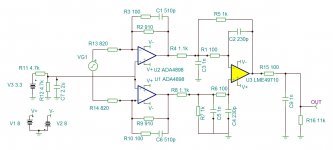
Regarding the output stage itself, it is based on a standard 3-opamp design. AVCC Vref for left and right channels are tied together in the output stage, and in the dac it was designed for, which audibly reduces stereo separation.
The output stage is designed to use an OPA1622 in the differential summing position, with the OPA1622 mounted on a DIP-8 adapter. The opamp choice and the choice to mount it on an 8-pin adapter are both mistakes IMHO. The opamp is really for driving low-power headphones with low distortion, not the best choice for output stage differential summing. Also, it is a 10-pin device that needs a reference pin tied to ground for lowest distortion. An 8-pin dip adapter can't ground the pin properly.
Since there is a dip socket for the differential summing opamp it is possible to use another opamp instead, but the resistor values around the differential summing opamp are too low for other opamps besides OPA1622. The resistors were optimized for lowest noise, not for lowest distortion or nor for good compatibility with more suitable opamps such as OPA1612. Wish it were otherwise.
In short: Sorry, but not recommended.
IMO the I/V stage should be as close as possible to the DAC itself and on the same ground plane...
Close. The ground plain should be uninterrupted between the dac chip and the output stage. IME there is a little RF coming out of a Sabre dac and some attenuation of that can help SQ as I have described before. I used twisted pair wire-wrap wire running along the ground plane between the dac chip and I/V opamps, one TP for each channel. That eliminated mysterious excess heating in the opamps. OTOH, AVCC opamps right next to the dac chip were not affected by otherwise unaccounted for excess heating. BTW, I observed the same excess heating in Ian's output stage I/V opamps when the output stage was mounted on the RPI stack. When I separated it using a folded ribbon cable, distortion was lowered and excess heating reduced. Unfortunately, I don't have equipment to measure the hypothesized RF, but there are certainly reasons think its there. I also once found a little RF on the output of the differential summing opamp that I couldn't find anywhere else. Adding some HF signal filtering caps made it go away (so far as I could see on a scope). That's why I recommend output stages with some real poles, caps to ground, at the input of, and as a part of, the multi-feedback filter that is included in a standard 3-opamp output stage differential summing stage.
I would add that I have not seen the RF heating issue with AK4499 I/V opamps. Just mentioned by way of comparison.
Last edited:
Thanks for the comments .
it's a shame there is no pcb for the output stage.
I think many would be interested
Serge
I use a Twisted Pair Ivy as the I/V from the DAC chip. Powered separately from the DAC linked together via two twisted pairs obviously as short as possible. I may consider using long pins to join the two vertically at some point.
Is it the last Schematic for the output stage ?
You could use that one, which I did, or you might want to use the parts values in the schematic below which is said to be of a Topping D-10. Same basic idea but filter values are a bit different.
Also of similar importance is the AVCC supply. Using opamp as buffers following a low noise regulator works quite well. Its also what ESS recommended early on. There is a schematic for our version attached to post #3003 in this thread.
Both the output stage and the AVCC supply need to be on same ground plane as dac chip. Running ground wires between separate boards is not ideal.
Attachments
Last edited:
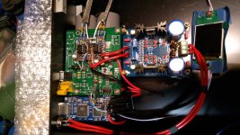
Finally got the dac to work with a new board! (First board were slightly defective.) That is also the reason some of the wires is somewhat melted since I've had to solder some of the parts several times. I belive in super short wiring so 2 LT3045 in placed right under the pcb together with 2 LiFePo4 32700 batteries(dual mono supply). Whole dac is powered by three outboard linear regulated supplies. One +-15V, the 5V supplies shares casing, but still a proper cable spaghetti
I've only listened to it for 6 hours but the sound is holografic with depth that I've haven't had before. So for now I'm very happy with it working and didn't let the magic smoke out!
I've only listened to it for 6 hours but the sound is holografic with depth that I've haven't had before. So for now I'm very happy with it working and didn't let the magic smoke out!
Attachments
It essentially has all the same sound quality problems as the original one and can benefit greatly from all the same fixes.
.
Hello!
Is there a summary of “the fixes” somewhere in this thread?
Thanks
Hello!
Is there a summary of “the fixes” somewhere in this thread?
Thanks
ES9038Q2M Production
A few months ago i opened this thread , it's for "beginners" and there are not all the Mark4 mods .
Serge
Hi!
I am not an audiophile listener and stream my music almost exclusively from Spotify (high res) via a Google Pixel 2 XL (capable for all codecs), but I would like to improve my setup for this.
Amplifier: NAD304
Boxes: Q Acoustics 2020i
Sub (active): Q Acoustics 2070i
Originally I bought a cheap DAC with BT, but the board arrived defective: DYKB 12AU7 Rohr CSR8675 Bluetooth 5,0 Audio Empfanger Bord ES9018 decoder DAC 12s signal APTX AUX fur 12v 24v auto Verstarker-in DAC aus Verbraucherelektronik bei AliExpress
Thought about ordering this one, but I'm not sure: Buy Products Online from China Wholesalers at Aliexpress.com
Any tips?
- Home
- Source & Line
- Digital Line Level
- ES9038Q2M Board