Mark, how warm would you estimate the opamps got in celsius? What is normal opamp temps? I only have opamps for virtual ground, and they are driving 2 amps. I would estimate mine reached 40C at full output..
Mark, how warm would you estimate the opamps got in celsius? What is normal opamp temps?
Sorry for taking some time to respond. Don't know the exact temp, but if no RF heating then the opamps are very comfortable to touch, not much above room temp.
Originally noticed the issue with the first modded ES9038Q2M dac where the output stage opamps seemed much warmer than could be accounted for given the expected power level was rather low. The AVCC opamps were located very close to the output stage opamps and the same type of opamp but were much cooler. No reason to expect the difference in temps yet the output opamps were so warm I put some heatsinks on them.
In other similar dacs I have seen a range of output stage heating symptoms ranging from pretty-suspicious to no-more-than-expected. When possible to physically separate the output stage from the dac chip (including on the same ground plane or if using some kind of extender) excessive heating seems to correlate with output stage proximity to dac chip. Never was able to capture proof of RF using a 100MHz scope though. Presumably, it would be very low level and or noise-like in nature given the failure to show up on a scope.
Is there a summary of “the fixes” somewhere in this thread?
Hi AMB4,
There is not an enumerated list that I specifically recall.
If it helps, briefly fixes may include:
* Output stage
* AVCC power supply
* Clock replacement
* Add more and better 3.3v regulators
* Opamp power supply quality
* Reprogram DAC chip I2C registers
* Replace DAC board passive components
* Consider use of upsampled DSD I2S input source, such as AK4137
All in all, it can be a lot of work to do everything. Most people who decide to go on an ES9038Q2M DAC modding journey have chosen to do a few mods and leave it at that. No worries about needing to do it all.
If you have more questions, happy to try to help if I can.
Thanks for the reply Mark! I measured mine with an IR gun and they were only at 29 and 30C so hopefully no oscillation.
I'm current trying out several different ways of connecting the earth from the different psu together. I started with a star ground which gave no hum but slight static distortion noise. Now I've put AVCC on each different transformer and put the Amanero board and the rest of the DAC on a new transformer. Opamps have its own transformer. Connecting it like this gave slight hum so now I'm trying out a different grounding scheme. Either the hum comes from the cheap trafo (running the Amanero and logical chips) through wounding capacitance or the grounding scheme is worse. I try to keep each ground loop separate and as short as possible, but also to keep loops away from the dac chip, AVCC and output.
Have anyone found a perfect star ground solution? Which parts of the circuits should I prioritize? I think an R-core trafo for the opamps would eliminate some problems but they are quite large and costly. I'm interested to hear which solution you guys found to work the best!
Impulse60,
Not sure what you want to do about the ground related hum problem.
IME, using multiple random transformers is likely to bring trouble. Probably best to use one R-Core with +-15 (or whatever voltage you want) and maybe a couple of 9v AC windings. Then with a dac board, probably best to use a ground plane as much as possible rather than star ground. Too much RF running around for low frequency grounding approaches, might be the philosophy. As always, Henry Ott is your friend there with his very practical book on Electromagnetic Compatibility Design.
Right now we are kind of starting out blind trying to offer ideas. If we have a better idea of your present hardware interconnection situation and some description of what you have tried so far and the results you found, that might help. A sketch out a layout drawing of your grounding scheme, sort of part schematic and part to-scale mechanical drawing could be very useful. Otherwise, we may be left to talking in very general terms.
Last edited:
I just ordered an R-core transformer with +-15 and a couple of 6V windings. I plan to use this for opamps and the dual 6V for the AVCC. I'm thinking a star ground between opamps and AVCC on the dacs ground plane. Are all these taps centered around the same ground on an R-core?
The second dual powersupply I already have will be used for 1.Amanero and 2. on rest of the dac board. This psu uses quality transformers so these might not need a star ground with the rest. The Amanero has an LT3045 and so does the stock dac crystal, and this complicates the picture even more. The AVCC also have each own LT3045 with a battery in parallel. I haven't experienced any problems with RF, the opamps have a thick grounded plate underneath and I have smd film caps very close to the opamps power legs and feedback. Since I've raised the gnd plane none of the current loops on the dac gnd plane will interfere.
I've read some pdfs on RF and ground loops but I have a hard time seeing how ground loops works in different transformers, especially with different voltage tabs. I know its impossible to visualize my setup so I was hoping for some general solutions which might benefit other members of this thread also. I guess I'll just have to hope for the best with the R-core solution and just use trial and error until it's silent and still sound good.
Hi Mark.
I am delighted to follow your work. It is interesting to see the measurements of the dependence of THD on the frequency and on the input level in the range 0 .... 80 dB at a frequency of 1 kHz.
I am delighted to follow your work. It is interesting to see the measurements of the dependence of THD on the frequency and on the input level in the range 0 .... 80 dB at a frequency of 1 kHz.
Are all these taps centered around the same ground on an R-core?
All the low 6v or 9v windings of the Chinese R-core transformers are separate from each other. The 15v outputs may either be from two separate 15v windings or from one 30v center-tapped winding.
For windings that are separate you can define the common ground between them, if any, wherever you deem best. For center-tapped windings, the center tap will become the ground or common for the +-15v regulators.
Hope that kind of makes sense. Since you can decide where to tie the various regulator outputs together to make a common ground, there is a lot of existing thinking about how to best do that. Usually, it is done at the output of the regulators, wherever the power supply is located. However, in one dac project I made an exception to that and tied grounds together at the dac board ground plane only. Worked fine in that case. Others may have more to say on the issue, we'll see.
Last edited:
Hi Mark.
I am delighted to follow your work. It is interesting to see the measurements of the dependence of THD on the frequency and on the input level in the range 0 .... 80 dB at a frequency of 1 kHz.
Hi UAN,
Thank you for your interest. 🙂
I sort of presume you are referring to the 'ESS hump' issue when you mention harmonic distortion dependence on output level? If so I would mostly say at this point my interest has mostly moved on to AK4499. However, I might be willing to have a brief discussion about ESS distortion if you want.
Thanks Mark for the answer.
I am really interested in the "Hump ESS" problem and you probably dealt with this topic. Over 500 pages of discussion of your wonderful
ideas and projects, it is difficult to find the right one. Therefore, please briefly outline the main causes of this problem and ways to solve it.
Please excuse a noob question, but will this work with coax output from Philips CDB 630. I realize I will need a +/- 15Vdc power supply. I'm new to all this digital stuff.
Please excuse a noob question, but will this work with coax output...?
Presumably, the coax output is SPDIF? If so, the DAC supports it.
However, this DAC's sound quality isn't too good until after it has been somewhat modified.
Thanks Mark for the answer.
I am really interested in the "Hump ESS" problem and you probably dealt with this topic.
Mostly, the hump problem has been discussed in more detail at another audio website: AudioScienceReview (aka ASR).
The first 'fix' offered over there involved removing the 1.65v Vref offset from the I/V opamp outputs. Turned out that didn't fix it for everybody. A later fix involved carefully adjusting I/V stage component values, using an FFT display of nonlinear distortion to help choose component values that minimize the distortion. Even so, the exact component values needed are believed to be dependent on the particular dac circuit layout and maybe other unstated implementation details. It means every dac design would need to be individually optimized. A couple of related links: ESS THD ‘Hump’ Investigation | Page 14 | Audio Science Review (ASR) Forum
How to Fix ESS Hump on SGD1 and LA-QXD1 | Audio Science Review (ASR) Forum
While all that was going on, in another thread here Scott Wurcer revealed that at some point ESS asked him to confidentially take a look at an ESS dac they sent him to see if he could find any problems (Scott is friends with ESS's VP of engineering). Scott said he found a few problems and expressed some concern that other people hadn't found them since he felt they were pretty basic. This apparently happened before the latest ESS chips came out. Maybe around ES9018(?), not sure.
Not too long after Scott posted about the above, in another thread he posted an image from a document ESS sent him that he said was old enough that it would probably okay with ESS to share. I will attach it below for reference.
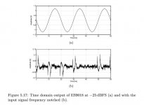
Scott Wurcer later suggesting investigating the newer ESS dac distortion by running a sine wave through it at a low level, then running the analog output through a notch filter in order to take a look at the time domain distortion waveform. I think he may suspect that the same anomaly shown in the attached pic may account for present day hump distortion. If so, it is obviously an error inside the dac chip, since it is too random in occurrence to be caused primarily by the I/V opamp.
In anther forum thread John Westlake, a well known commercial dac designer opined that he suspects the characteristic sort-of-unnatural sound of ESS dacs is probably due to something in the modulator (not a direct quote, but words to that effect IIRC).
Hopefully, that's enough history on the subject to satisfy curiosity.
Bottom line for me: Move on to AK4499. Its a better dac chip, IMHO.
Attachments
Mark, thanks for the detailed answer.
I am familiar with the discussion on the AudioScienceReview website. I have a Topping D50, the new D50s has no hump. They have different ratings for I / V and LPF components. Before starting the modernization of my D50, I collect information about the hump problem from other sources. I measured the distortion spectrum on the hump, there are only odd harmonics with a level of 70 ... 75 dV. This explains the excessive brightness of this DAC.
The AKM DAC evokes more naturally, I have already seen this.
Thank you again for the consultation, creative success!
This explains the excessive brightness of this DAC.
Some of it, perhaps not all of it. Sometimes these dacs have multiple problems. Only way to know for sure seems to be to fix each problem one by one until the dac sounds good to you. For me with ES9038Q2M that was very difficult, among other things only DSD ever sounded to my liking.
Last edited:
After 1 year i brought this dac from dust world 🙂). I want to compare it it full Ian streamer stack accu suplied with China output transformers.
My version is with 7 regulators. Because i use just 8,4v lion acuu supply i cant use AVCC regulators like here proposed. My output stage is Bisesik transformers.
I replaced lt3042 plus transistor version for both AVCC with Shunt regulators set to 3,3v 50ma. It is firs regulator that shows no signal amplitude noise patern at AVCC pins. Improvement in terms of dynamic and drive. Speakers disappears, sound is fuller. That sound is fuller in right direction is also dac optimisation on other stages. Stock is really thin, harsh and light sounded with same output transformers as now. In this configuration is this little dac quite good. It is quite close to heavy modified es9038pro on coaxial input.
For not hi end appetites, it is worth to modify it.
I think for 90% of diy people, it is not need for upsampler board, because 10times more expensive Ian stack plays in same dpll setings and same soft linear filter not so dynamic and easy flow than this one. Details are in the same league, at sync mode and dpll set to off, with Ian sound is more 3d, and relaxed, little softer but quite laid back, maybe more listenable for long term easy listening.
Shunt regulators for AVCC are upgraded version of regulator from post 26, made by Stormsonic.
https://www.diyaudio.com/forums/pow...ultimate-voltage-regulator-3.html#post2520626
Big hint. All supplies that comes on dac must be clean as possible. This little dac has poor grounding. Any noise that will come trough big caps to ground will mess an polute all supply pins. Therefore i only use Lipo supply.
It is first regulator that shows no signal amplitude noise pattern at AVCC pins.
How are you showing signal amplitude noise pattern on AVCC pins, with FFT?
With scope.
Choose one frequency...i took 1khz 0db from my test cd and i always measured 1 khz small uV signal on avcc pins. Much larger as regulator noise. And if i use big filter caps near dac on other supply pins then noise was gone trought capacitor and was also visible there. Avoid big filter caps near this dac if supply is not clean. Grounding is poor as i told previous. This time it was clean. I plan to use also on es9038pro but there I need min 150mA what is a big problem...space, heat..
Maybe that regulator that you use also don*t show that pattern what is good. If yes than is still room for improvement.
Last edited:
I changed clock to ndk 80mhz. Sound is fuller and smother. Maybe first seconds feeling of less highs but music is more layered. Dynamics goes more right left direction not so into your face. But one problem... 44.1khz input now shows 48khz on Dac display. But 48khz input shows right number 48khz. Any explanation?
Stormsonic was not reachable to ask him if i can reveal more infos about regulators. I will ask him if he can do that here.
Stormsonic was not reachable to ask him if i can reveal more infos about regulators. I will ask him if he can do that here.
Last edited:
- Home
- Source & Line
- Digital Line Level
- ES9038Q2M Board