I finally got around to auditioning my "little giant" TDA 1387 board in a decent system. I let the dac burn in for about 8 hours over a few days. Mine is powered from the on board regulators, I just hooked up two torroids to feed it AC. Feeding it through the coax input from the coax out of a CD player. The system I used is pretty easy to hear differences, Pass VFet amp fed by a Salas DG3 preamp. I compared it head to head with a AK4490 DAC from JLSounds, using an isolated Xmos USB fed from separate power supplies. Used Foobar running DSD at 32 bit. I used the same CD in the CD and in Foobar and switched between the DACs using the source selector on the preamp. The TDA1387 had a slightly lower output which I compensated for when listening. The base on both DACs was about the same as was the imaging. The soundstage was large for both also. The AK4490 had a lower noise floor and more mid and upper end detail, and sounded a little bit more liquid. That said the TDA1387 was very impressive and easy to listen to, the vocals were nice and smooth. It seemed to sound warmer, but I think the impression of warmth came from the more muted detail in the mids and highs (NOS droop ?).
That said I think it sounds great for the money. The board looks nicely made, but seems that it may be difficult to modify with all of those teeney weeny SMDs. The AK4490 cost many times more to put together and I think that's its a nice DAC, I do enjoy it. Nothing really jumped out at me regarding multi bit NOS vs delta sigma, they sounded a lot alike to me. I have another R2R cheapy NOS (AD1865) from the same maker on the way, I'll see how that sounds in a few weeks.
That said I think it sounds great for the money. The board looks nicely made, but seems that it may be difficult to modify with all of those teeney weeny SMDs. The AK4490 cost many times more to put together and I think that's its a nice DAC, I do enjoy it. Nothing really jumped out at me regarding multi bit NOS vs delta sigma, they sounded a lot alike to me. I have another R2R cheapy NOS (AD1865) from the same maker on the way, I'll see how that sounds in a few weeks.
I am having no joy with this build. I am guessing I may have soldered the ICs incorrectly or overcooked them on the hot plate. Also, when I configure Volumio it asks for which DAC is installed. Quite a few listed, so perhaps that is also a problem.
Hi David! Nice to see another build in the wild, even if it's not currently working. Hopefully we can get you squared away! (I can't remember, did I send you that board, or did you fab it yourself?)
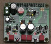
*** I typed up everything below, but as I was reviewing, I noticed something in your pic. See the two orange circles in the upper-right in the image below? You need to jumper those (I use left-over component leads). The board has multiple ground planes, this is the "star" connection point for those separate grounds. If you don't jumper those, much of the circuit will be open.
") So that's step one. After you address that, I'd suggest running through some of what I wrote below, at least the powered-off sanity continuity checks.
So that's step one. After you address that, I'd suggest running through some of what I wrote below, at least the powered-off sanity continuity checks.Anyway: it's been a while since I've used Volumio, and it somewhat abstracts the low-level details, which is what I'm more familiar with (since I do everything from the commandline using DietPi). That said: does Volumio offer a "hifiberry-dac" option, or something similar? At the low-level, that is the "device_tree_overlay" (also called "dtoverlay") you want for use with this DAC. Here's what you can do: make the setting change, reboot your RPI. Then, go into the shell via ssh, and run this command:
Code:
egrep '^(dtoverlay|device_tree_overlay)' /boot/config.txt
Code:
root@basement-music:~# egrep '^(dtoverlay|device_tree_overlay)' /boot/config.txt
dtoverlay=hifiberry-dac
Hopefully that gets you going on the RPI front.
Next up, with the board not powered on, you can do some basic sanity checking with your continuity checker. See the image below, I marked it up a bit. Check for continuity (zero or near-zero resistance) between the following tda1387 pins:
1 - BCK
2 - WS
4 - GND
5 - VDD
In other words, pin 1 on both tda1387 chips should be connected. The same goes for the other pins listed above.
Then you can also check for continuity between the following HC86 pins and the corresponding tda1387 pins:
HC86 pin 3 - tda1387 pin 1 (BCK)
HC86 pin 6 - tda1387 pin 2 (WS)
HC86 pin 8 - tda1387 pin 3 (one chip only)
HC86 pin 11 - tda1387 pin 3 (the "other" chip)
HC86 pins 7 and 10 - GND
HC86 pins 13 and 14 should be connected
Next, for each tda1387 chip, check that no pin is shorted to any other pin. This is very tedious! Do the same for the HC86 pins, noting the above pins that are supposed to be common (7/10, 13/14).
Looks like you figured out (or maybe I told you?) about the tl431 silkscreen being misleading. Next step is to power up the board and check voltages. Pins 13 and 14 (yellow circle) of the HC86 should be at 2.5v.
On the tda1387 ICs, pin 5 (orange circle) should be at 5.0v.
What kind of transistors are you using for the "active" I/V? Where I've made the four circles in red, those should be at 2.8v - assuming you're using BC857, BC807 or similar. Do make sure you have the leads soldered correctly! In particular:
Emitter connects to the ferrite bead
Base connects to the 22R
Collector connects to the RC network
Hopefully we get you playing sweet sweet music!
Attachments
Yes the boards you sent Matt, thank you. A big oops on the jumpers. I will try that, perhaps it will play, fingers crossed. I will double check my work and the voltages. You are most kind to lay out the points to check. Volumio does offer a hifi berry dac.
I will work through this tomorrow during the day.
Thanks
David
I will work through this tomorrow during the day.
Thanks
David
Thanks for these suggestions, Matt. Added jumpers, check continuity and voltages. All good. I have a dedicated Pi, Kali, Piano rig. In order to leave that setup alone I ordered another Pi and will go the DietPi route you are using. I think this will be easier than going back and forth with the only Pi I have in house.
So new Pi should be here on Thursday. Plus I get to learn some programming.
So new Pi should be here on Thursday. Plus I get to learn some programming.
I finally got around to auditioning my "little giant" TDA 1387 board in a decent system..... the TDA1387 was very impressive and easy to listen to, the vocals were nice and smooth. It seemed to sound warmer, but I think the impression of warmth came from the more muted detail in the mids and highs (NOS droop ?).
....I have another R2R cheapy NOS (AD1865) from the same maker on the way, I'll see how that sounds in a few weeks.
my little giant arrived yesterday morning (after re-ordering from Taobao - slightly cheaper, with the seller's transformer.).
After 24hrs burn in, my impressions match yours. The mid range is laid back, gentle, smooth... and the sound lacks the dynamics and fine detail other DACs can produce, but admittedly they cost far more.
I guess part of the issue with the treble response is the AC coupling caps, and it might be beneficial to trim out the DC offset so they can be bypassed. Re-evaluate after that.
The rectifiers on the underside are DB207S. Seems they are very average parts so, based on my previous experience, the DAC should sound more dynamic with some ultra fast recovery diodes like MUR120 + pf snubbers. Might be worth trying to see if it gives this DAC more punch.
Anyway, only 2 obvious "weaknesses" and 2 possible "solutions" ... not bad at all.
It sounds more accurate than the TDA1543s I've used. I got a bunch of them years ago and measured them to pick the best - tried 8x, 4x, 1x... a pleasant sound but not so good I kept them. The 1541 I had sounded better but I re-sold that too, which I now regret because it would have been good to compare to this TDA1387.I'll be interested to hear what you think about the AD1865. I cancelled my order for that too - might re-order if you think its decent.
So, Matt, new Pi arrived and after a number of hours, no joy. I am really lost in the programming side of things. Volumio with the Allo products is mostly plug and play.
I did check out DietPi and left that more confused, though it is obvious it offers much more to the user.
One, I don't really know how to drill down in Volumio, meaning I don't know where to install the line of code you wrote on the previous post.
If "Stellar" reads this I would be interested in knowing how he was able to get Volumio to play.
When the Pi and TDA1387 board are connected i can hear music very faintly with a lot of static noise overpowering it.
Lastly, I did check my build and used your numbers and found everything to be ok, added the two jumpers. So it may simply be my build and the player software is working, which is why I would love for "Stellar" to comment.
Thanks
David
That works as expected.I guess part of the issue with the treble response is the AC coupling caps, and it might be beneficial to trim out the DC offset so they can be bypassed.
The I/V op amp output has a DC offset of -1.7V and it sees 2.8KR before the inverting input of the buffer op amp. Both OP42 op amps btw if you don't have this DAC. To roughly match that current, feed -12V via 20K potentiometer to pin 3 of the buffer, the non-inverting input. For this DAC, to make this work, lift pin3 from it's pad first of course (it connects to ground).I trimmed out the DC offset and measured the values at 17.8K from -12V to pin3 and 1.7K from pin 3 to gnd. ( I actually used a 10K smd resistor and 10K trimmer to make trimming a little more accurate). The -12V is from a TPS7A3xx regulator supplying the op amps so it's already clean but will be modulating a little due to the demands of the op amp. I haven't added a filter capacitor for this yet - from pin 3 to ground - I'll investigate how values for this cap affects start up and shut down pops due to time constant.
Removing the cap not only allows greater transparency, it allows DC current to flow out of the op amp so it's always on.
Last edited:
So, Matt, new Pi arrived and after a number of hours, no joy. I am really lost in the programming side of things. Volumio with the Allo products is mostly plug and play.
I did check out DietPi and left that more confused, though it is obvious it offers much more to the user.
One, I don't really know how to drill down in Volumio, meaning I don't know where to install the line of code you wrote on the previous post.
If "Stellar" reads this I would be interested in knowing how he was able to get Volumio to play.
When the Pi and TDA1387 board are connected i can hear music very faintly with a lot of static noise overpowering it.
Lastly, I did check my build and used your numbers and found everything to be ok, added the two jumpers. So it may simply be my build and the player software is working, which is why I would love for "Stellar" to comment.
Hi David! Sorry for the frustration! But I'm still hopeful we'll get this going, don't give up yet!
So, first question: are you actually using DietPi or Volumio currently? I assume you're using Volumio since you have something playing (even if it's garbled)... if that is true, are you using the "hifiberry-dac" device selection, as discussed above?
When I talked about looking at the config file, that was more of a sanity/diagnostic step. I can't be 100% sure, since I'm not using Volumio, but I'm 99% sure you don't actually need to log into the Linux shell as I suggested; I think GUI control is probably fine.
Can you tell me, what MPD client are you using to control playback? Are you using the Volumio web interface? Or an MPD app, such as M.A.L.P. on Android, or Auremo on Windows, or something else (dozens of possibilities here)? I'm just trying to get a sense of your environment.
Switching gears, back to DietPi: by design it is a very "barebones" Linux distribution for Raspberry Pi, and necessarily requires you to manually do much of the setup that Volumio does automatically. This is all done by logging into the shell (i.e. command-line interface) via ssh. You'll have to install and configure MPD; and also set the right dtoverlay (as suggested above). Before I go into too much detail, are you familiar with using ssh to login to a Linux shell? That's really step 1 with DietPi.
DietPi is great if you're really comfortable with the Linux shell (I've been using Linux for 20 years now, so it's second nature to me). But if that's not true for you, my suggestion is to stick with Volumio for now, so we can focus on one thing at a time.
Looking at the Volumio Quick Start Guide, I'm looking at the third picture down, the text just above it says, "The helper third screen : Configure your DAC". For that, you want to say "YES" to "I have an I2S DAC", and for "Select your I2S DAC", according to this page, I expect there to be a "hifiberry-dac" option (it probably shows up as "HiFiBerry DAC"). So try that. Note there are a number of HiFiBerry selections, so make sure you pick the right one.
Hopefully Stellarelephant can jump in and confirm, but I'm pretty confident that's the right way to do it. It really shouldn't require any special tricks. I can give Volumio a try, but it will be a while before I have time for that.
Lastly, when you say, "I did check my build and used your numbers and found everything to be ok", just to be clear: did you check all the voltages with the board powered up, after soldering those jumpers? If so, it might indeed be a subtle soldering issue somewhere. But let's get on the same page with all the above before we go down that road.
Edit: another fairly easy test: do you have a single-ended amp you can test with? As you can see, the outputs on the DAC board, for each channel, are NEG-GND-POS. You can just use "NEG-GND" or "POS-GND" from each channel into a single-ended amp (i.e. leave NEG or POS open). In fact, ideally, you should try both. If one is not garbled, and the other is, that suggests a solder issue on the DAC output side. (And when you get this all working, for fun, you can run one channel from NEG and the other from POS to hear what it sounds like when the channels are out of phase. It's interesting but not pleasant!)
Last edited:
Success Matt. It was a case of BE (builder error) on my part. Your suggestions were most helpful in steering me in the right directions.
Currently have it playing through an Impasse preamp into a Pass M2, very nice. I am going to reorder the parts I don't have and build another!!
Thank you very much for your help.
Regards,
David
Currently have it playing through an Impasse preamp into a Pass M2, very nice. I am going to reorder the parts I don't have and build another!!
Thank you very much for your help.
Regards,
David
I can't see anyone has measured the MHz noise coming out of one of these TDA1387 chips so I put my little giant on my ancient giant scope. I found 400mV at 5.5MHz (1/3 of f clock, 18.4MHz). There may be more waves higher up but my scope can't measure much higher than this in practice. That's kind of irrelevant anyway - the take home message is that the DAC design has no filter in the I/V stage but it evidently needs one.


Last edited:
I went through the whole spectrum, albeit fairly quickly, but I didn't find any surprises. It is the usual mix in the audio band and that decreases in amplitude as the frequency dial notches up - no stand out surprises on the way - but it'll be interesting to see what lurks way up high or if the SA can catch stuff I've missed, harmonics etc. That scope trace is pretty clean though. Certainly, an SA graph is far easier to see what is happening and much less laborious to do. What SA did you get?
Last edited:
One more note on this little giant - the buffer circuit (top right hand side of the pic) has a low pass RC (after the grey electro cap) and there’s a low pass in the op amp feedback loop (blue box cap and two resistors). The feedback loop is 1k in series with 820pF (blue box) and they are in parallel with 2.7k (above the blue box). The RC is 1.7k and 2.7nF (orange blob). Overall, this is a multiple feedback low pass filter with a gain of -1.6, a Q of 0.56, a corner frequency of 65kHz, and a 0.45dB cut at 20kHz. Reducing the 1k (the one in between orange blob and blue box) to 370R gives Q=0.49, f=107kHz, and -0.3dB at 20kHz – that’s a little better for the sake of one resistor change. Thanks matt for the pic - that's your excellent pic
An externally hosted image should be here but it was not working when we last tested it.
Last edited:
Success Matt. It was a case of BE (builder error) on my part. Your suggestions were most helpful in steering me in the right directions.
Currently have it playing through an Impasse preamp into a Pass M2, very nice. I am going to reorder the parts I don't have and build another!!
Thank you very much for your help.
Hi David, that is awesome! I'm glad I could help!
What was the actual problem?
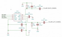
OK, the overthinker strikes back... I just bought 5x pices for less than 2$ at ebayOK, one more option: the tda1387 chip itself is cheap, you should be able to source them for $1/each or less. A very basic implementation can be created on breadboard for very little money. Something like this:If you have all or most of those parts on hand, you could whip up a basic tda1387 DAC with passive I/V in maybe an hour or two. If you have to order all the parts, it might be cheaper just to get the x4 USB DAC I mentioned above. But the idea is the same: it gives you a taste of the tda1387 with minimal cost-risk. (The DIY fun factor is off the charts for this option!)
- 5v power supply (e.g. USB charger)
- 220uF (or more) 10v PSU decoupling cap
- 100nF 50v X7R (or C0G) PSU decoupling/high freq filter cap
- Capacitor for pin7/VREF (1uF per datasheet, or 1000uF or more for better bass)
- Two 2.2uF (or greater) output caps for DC-blocking (ideally film)
- Two I/V resistors (in the range 2.7k to 3.5k)
- Two 1.5nF film or ceramic caps as a basic high-frequency filter
Since I had some passive components around to use in a cmoy amp I thought I could give it a try... I'll give some guidance on the schematics though, have no clue where to start from for this very basic implementation on a breadboard. Any link anyone? Thank you!OK, the overthinker strikes back... I just bought 5x pices for less than 2$ at ebay
Let the fun begin! I whipped up a quick schematic for you, see attached. I matched the components in the schematic to my original parts list:
- 5v power supply (e.g. USB charger) - "+5V" on schematic.
- 220uF (or more) 10v PSU decoupling cap - C2 on schematic.
- 100nF 50v X7R (or C0G) PSU decoupling/high freq filter cap - C1 on schematic.
- Capacitor for pin7/VREF (1uF per datasheet, or 1000uF or more for better bass) - C3 on schematic; I made it a polarized 1000uF/6.3v, but you can do pretty much anything here, datasheet minimum is 1uF ceramic.
- Two 2.2uF (or greater) output caps for DC-blocking (ideally film) - C6, C7 - I indicated MKS, but whatever you have on hand is probably good enough for this test.
- Two I/V resistors (in the range 2.7k to 3.5k) - R1, R2
- Two 1.5nF film or ceramic caps as a basic high-frequency filter - C4, C5
Hopefully "TO_RIGHT_AMP_CHANNEL" and "TO_LEFT_AMP_CHANNEL" are self-explanatory.
On the left is the I2S input: BCK, WS, DATA. I assume you have some kind of device that outputs I2S (raspberry pi, Amanero, XMOS, etc).
Let me know if you have any questions!
Attachments
Matt I went back through the board and reheated each IC pin also I had installed R3 with the 390R smd. Failing to read indicated I needed 0R there. BE!!
I am currently using it with an Anker USB battery. Sounds really nice very laid back.
Try listening to Hummel's trumpet concerto in E flat third movement the rondo, played by Wynton Marsalis. Really shines.
I am currently using it with an Anker USB battery. Sounds really nice very laid back.
Try listening to Hummel's trumpet concerto in E flat third movement the rondo, played by Wynton Marsalis. Really shines.
Well I gotta wait for the IC's to arrive from China, but at least I made a step forward. Now looking at my shelf I realised I might not have the exact parts and still lack some others. See below.Let the fun begin! I whipped up a quick schematic for you, see attached. I matched the components in the schematic to my original parts list

I will salvage more passives from an old DVD I have in the shelf, otherwise will have to buy some at ebay (Mouser for less than 50$ is too expensive)
Yup, hopefullyHopefully "TO_RIGHT_AMP_CHANNEL" and "TO_LEFT_AMP_CHANNEL" are self-explanatory.
Yeah, got a RPi2 around.On the left is the I2S input: BCK, WS, DATA. I assume you have some kind of device that outputs I2S (raspberry pi, Amanero, XMOS, etc).
I think that's all for now. Just need to salvage more passives and get the ICs to my door.Let me know if you have any questions!
Thank you again for all, the fun will begin shortly!

- Home
- Source & Line
- Digital Line Level
- tda1387 dac pcb "front end"