Thankfully I won't need to cut the fat GPIO power trace at top left since I already have made provision to send dedicated power to the board by NOT stacking the board atop my Pi stack and instead using GPIO jumpers for I2S and with power jumpers going to separate PSU.
Ahh, yes, an even simpler solution that doesn't involve physically altering the board!
I WILL try my hand at cutting the middle trace to get a dedicated 5V feed for the TL431 and I/V transistors (option #1). I will be using another one of Greg Stewart's modded Jamecos. Greg actually has the DAC for audition at present, so it'll be a week or so before I am able to try this.
Actually, perhaps a better approach is to simply remove R1, replace it with a through-hole resistor inline with your discrete supply's positive lead. Then you don't have to cut the trace on the board (you're "implicitly" cutting it by removing R1). It's easier and cleaner to re-solder an SMD resistor than to repair a cut trace IMO. That's a 1k resistor, which is a super-common value.
I have an LT3042 module that could be used to drop a 5V Jameco to 2.8V, for option #2 down the road. It isn't the best sounding regulator module in the world, but if it is superior to the TL431, perhaps it would give another SQ bump.
I'd be interested in learning about your results of that experiment. The TL431 is nice because it's cheap and easy to use; those are the main reasons it was chosen for this application.
Note there are different grades of TL431, that vary in their tolerance. I can't remember what grade I put on that batch of single-ended RPI DAC HATs (such as the one you have). I can't say for sure, but I suspect I may have gone with a cheaper/lower-grade TL431... if so, it might be worthwhile to get the best grade ("B"/0.5% IIRC) and upgrade the one on your board.
Your new balanced Pi Hat looks cool, and the added power and I/V flexibility make it quite attractive. Impressive 3D model too! I have not heard passive I/V yet. Are you intending to use it like this yourself or to follow with a separate I/V board? At any rate I appreciate the modular approach. I have been itching to build the new Pass B1 NuTube buffer...I wonder how that would pair up with passive I/V. All my gear is single ended. What will signal output voltage be for SE and balanced?
The design tool, KiCad, auto-generates those nice raytraced 3d models.
I will initially use it with passive I/V. I've only flirted with tda1387 in passive I/V form, never done any listening beyond checking that something works. So I want to see what passive sounds like. Maybe it's good enough for me? But right now I'm thinking of maybe creating a super-simple op-amp based I/V board, and also maybe trying to create a fancier I/V board with Abraxalito's filtering and discrete buffers. But for now, all that's just thinking out loud.
In general, the signal output voltage will depend on the I/V resistor used. Hopefully someone will correct me if I get this wrong, but I believe the math goes something like this: at 5V supply voltage, the tda1387 can output up to 1mA current. The output compliance is 3.5v (again with 5v supply), so our I/V needs to be chosen such that the output voltage never exceeds 3.5v. Using Ohm's law, V=IR, we get 3.5 = 0.001*R. Solve for R, the biggest IV resistor is 3.5k Ohm. A peak-to-peak voltage of 3.5v, results in an RMS output voltage of about 1.25V (divide 3.5V by 2.8, see here).
I'm personally OK with lower voltage coming out of my DAC, so I use a 1k resistor. So: V = 0.001 * 1k = 1V (peak-to-peak). 1V/2.8 = 357mV RMS.
The above exercise is for a single tda1387 (for a single-ended output signal).
My original front-end board had jumpers to configure for single-ended or balanced output. I didn't have room for jumpers on this new design, but you could go strictly single-ended with a little bit of board hacking (cut a trace, jumper a wire on HC86). Or you could keep the "cold" part of the circuit active, and run it to ground; or give it a "dummy" load like Abraxalito is doing on his lingDAC.
I think that 1.25V RMS is the most you'll get from the tda1387. Even if you parallel the chips, the output voltage still won't exceed 3.5V (voltage in parallel is the same), so that limits the RMS number.
You can go a bit higher than 3.5V by using more than 5V supply, as Abraxalito does. I believe he said it scales proportionally, so if you feed the tda1387 6V, the output compliance will be 4.5V (about 1.6V RMS).
Lastly, I believe since your goal is single-ended output, you could run the DAC in balanced mode, then convert to single-ended by use of transformers. Again, need real experts here to check this, but I think since you have a differential signal (i.e. signal plus its inverse), you could feed them to the transformer's primaries (wound in opposite directions), and have double the voltage output on the secondary side (assuming 1:1 transformer windings).
In fact, I've always wanted to experiment more with transformers, but the really nice ones are expensive.
Hi matt,
Just want to thank you for very good and very musical dac!
The SQ is Pleasant to the ear, warm and soft.
I can listen to it for hours and really enjoy it.
My setup is pi>IsolatorPi by ian>kali>balanced tda1387 RPI HAT DAC
Feed by linear power supply based on lt3045
P. S i didn't hear hiss sound from the dac, that you mentioned before.
Thank's again,
Yos.
Yosyos - that looks great, thank you for sharing! To my knowledge, you are the first person to do your own fabrication and assembly (at least, I think you are the first to talk about it). I'm also delighted to hear you are enjoying it.
Thanks again, and hope you continue to enjoy it!
Thanks again, and hope you continue to enjoy it!
In fact, I've always wanted to experiment more with transformers, but the really nice ones are expensive.
Matt, people seem to be happy with the Edcor PC600-15K, performance and soundwise. I believe it is inexpensive (under 10 dollars?) if you are in the US.
For those who haven't seen it yet, diyAudio's own Scott Wurcer has measured an Edcor PC600-15K as used in the First Watt M2, and built a SPICE simulation model that fits his measurements. So, if anybody was planning to put M2 into LTSPICE, your task just got a little easier.
The model for 6X gain {as Nelson Pass used in the M2} is on the left; Scott also modeled another way of connecting the Edcor transformer (that nobody has yet built into an amplifier) with 11X gain, on the right.
Here is the post: LINK
Questions? Scott is the guy most likely to know the answers.
I thought I should write this. I personally am not fond of making the dac differential/balanced by doubling the dac chips. While I enjoyed the dacs I made that way, I realized pure single ended is better when I went back to it.
The differential scheme changes the "harmonic signature" of the dac, for lack of a better term. Second harmonic is cancelled to a large extent, while third harmonic remains the same. This in my opinion (and that of many experts) is the opposite of what works well for sound. What seems to be desirable is dominant second harmonic, at a fair level (think tubes) and low odd harmonics.
I offer one short video and one article for consideration. It´s interesting material, altough not specifically about dacs. These mastering engineers are among the very best (Bernie Grundman and Bob Katz).
YouTube
Katz's Corner Episode 25: Adventures in Distortion | InnerFidelity
Thanks,
Alex
Matt, people seem to be happy with the Edcor PC600-15K, performance and soundwise. I believe it is inexpensive (under 10 dollars?) if you are in the US.
I actually have the Edcor TTPC15K/15K transformers. Doesn't look like they sell them any more, but I think they are practically the same as the PC-series that is currently available. I also have the Jensen JT-11P-1. (I wish I had the PCB mount version of those Jensens; their long skinny leads upset my neatness neurosis!) At some point I may have to pull these out of storage, and maybe get some lower-impedance Edcor PC series. Actually, to be honest, it's less about money-cost and more about time-cost. I have an ever-growing list of things I want to play with, but very limited time to actually do those things!
The differential scheme changes the "harmonic signature" of the dac, for lack of a better term. Second harmonic is cancelled to a large extent, while third harmonic remains the same. This in my opinion (and that of many experts) is the opposite of what works well for sound. What seems to be desirable is dominant second harmonic, at a fair level (think tubes) and low odd harmonics.
Do you know why this is? I.e., why does the differential scheme "selectively" cancel out 2nd-order harmonics? Do you recall what the rest of your system looked like when you made this observation? In my case, I generally have to switch amps when I switch between balanced and single-ended DACs. In other words, two variables change.
I wonder if there's a way to counter-act this, to get the best of both worlds?
At any rate, I don't think I can hear it. Although now that you mention it, I might start hearing it. 🙂
I still like having differential output as an option on my designs. Even if single-ended is the goal, it's easy enough to only populate half the circuit, or run the cold output into ground (e.g. with those pseudo-differential cables), or even do like Abraxalito and present a "dummy" load for the cold DAC(s).
So many ideas to explore, so little time!
Do you know why this is? I.e., why does the differential scheme "selectively" cancel out 2nd-order harmonics?
Matt, good question, i don´t recall having seen a mathematical proof of this. Should be interesting. It is important to make the distinction: the differential circuit doesn´t erase harmonics of the original signal, it cancels its own even harmonics. So if a circuit is clean enough, very low distortion, I suppose it´s no issue running it balanced/differential.
OTOH, if the circuit produces some harmonics, it might be better not to cancel the most desirable second harmonic.
My amp is similar to Juma´s, but I used LM3875 and balanced input (yes I use an amp with balanced input and a dac with single ended out and it works very well).
GC SuperSymmetry
The differential scheme changes the "harmonic signature" of the dac, for lack of a better term. Second harmonic is cancelled to a large extent, while third harmonic remains the same. This in my opinion (and that of many experts) is the opposite of what works well for sound. What seems to be desirable is dominant second harmonic, at a fair level (think tubes) and low odd harmonics.
I'm skeptical of this argument because while it works fine for harmonics of test tones (normally single sinewaves) it doesn't to me seem to make sense when music is being played.
According to reliable research (referred to in Belcher's WW paper going back to 1978) with music there are so many tones present that intermodulation distortion totally swamps harmonic. So do those missing 2nd harmonics translate directly to missing 2nd order terms with IMD I wonder? From a quick look at images of how intermod distortion occurs the third order products are going to be closest in frequency to the original tones (2f1-f2 and 2f2-f1) so it might be that third order IMD is the most audible, but why would the absence of the second order IMD (sum and difference) tones be undesirable?
Do you know why this is? I.e., why does the differential scheme "selectively" cancel out 2nd-order harmonics?
The way I look at it, its because the 2nd order (and all other even order terms) are in-phase on both the +ve and -ve signal wires, whereas the first, third, fifth etc remain 180o out of phase. So when the difference is taken between + and - those even order terms are the same on both sides and hence vanish.
I think the argument for differential is strongest when we consider power supply noise being cancelled in classA systems by such an arrangement. The cancellation doesn't happen if we run classAB though, contrary to what I've read elsewhere. So bridged chipamps don't benefit from supply cancellation unless heavily biassed into classA.
Richard, I heard the differences, so I just accept it.
BTW, I heard these differences before I read about them, so it was an "independent finding" 🙂
( I even told you in an email 🙂 )
I quote that article from Bob Katz:
He is a top notch mastering engineer. Works with a lot of minimalist, acoustic recordings. He is quite accessible via email, maybe you could have a more technical discussion with him if you wish. BTW his book "Mastering Audio" is very good.
Thanks,
Alex
BTW, I heard these differences before I read about them, so it was an "independent finding" 🙂
( I even told you in an email 🙂 )
I quote that article from Bob Katz:
I've known for many years that harmonic distortion can enhance depth and ambience, but this is uncanny—it's like there's a magic reverb chamber in the tube. The ambience is enhanced in a holographic way that's totally pleasant and not at all distracting from the original mix or performance.
He is a top notch mastering engineer. Works with a lot of minimalist, acoustic recordings. He is quite accessible via email, maybe you could have a more technical discussion with him if you wish. BTW his book "Mastering Audio" is very good.
Thanks,
Alex
BTW, in that quote, he is referring to pure 2nd harmonic distortion, no 3d harmonic component at all. His "Blender" was tuned to produce pure 2nd (he used a nuvistor).
When your circuit has a certain amount of second and third, and you remove the second harmonic only, the result is a very focused sound, emphasis on the foreground, and diminished ambience and depth.
When your circuit has a certain amount of second and third, and you remove the second harmonic only, the result is a very focused sound, emphasis on the foreground, and diminished ambience and depth.
I was re-reading the text and thought I should quote this as well:
In the article he is talking about adding pure second harmonic, while in our projects we are talking about removing the second harmonic by means of a differential circuit. The outcome however is similar IME. (Removing second harmonic = diminishing the qualities that he is talking about).
Thanks,
Alex
Which is precisely my impression as well.Adding the Blender subjectively brings up the bass, although the frequency response measures ruler flat to well above 100 kHz. So the harmonics add warmth and a sense of "fatter" bottom.
In the article he is talking about adding pure second harmonic, while in our projects we are talking about removing the second harmonic by means of a differential circuit. The outcome however is similar IME. (Removing second harmonic = diminishing the qualities that he is talking about).
Thanks,
Alex
The way I look at it, its because the 2nd order (and all other even order terms) are in-phase on both the +ve and -ve signal wires, whereas the first, third, fifth etc remain 180o out of phase. So when the difference is taken between + and - those even order terms are the same on both sides and hence vanish.
If true, wouldn't that then apply to all DACs run this way for balanced output (i.e. two DAC chips run in parallel, but one with the DATA line inverted)?
Looks like a lot of the newer sigma-delta DAC chips will do balanced out natively, I wonder if it applies to them as well?
I suppose the question was for Richard, but let me answer. If it is a differential setup (not parallel) then yes. You will see a degree of cancellation of even harmonics which depends on how well the halves match. The dac will probably have a third harmonic signature, and hence a sound which is different from a single ended dac (which usually has dominant second and diminishing higher order harmonics).If true, wouldn't that then apply to all DACs run this way for balanced output (i.e. two DAC chips run in parallel, but one with the DATA line inverted)?
I am assuming there is some harmonic distortion happening. With a modern chip it might be so low that it doesn´t matter anymore. Some people say the modern chips have other problems (for instance Thorsten Loesch, which includes an old chip in all his modern DAC products such as DP-777. His designs are single ended. It is suspected, not just by me, that the dac chip is the TDA1387!). I like DIY so I stick to the old chips and have a good result with them 🙂
To conclude, the principle we are discussing applies whenever you see a true differential output connected to a differential input. Some people seem go to extremes to avoid any "differential" in the signal path, and one of them happens to be a legend in the mastering business, very trusted (Bernie Grundman). He said he uses the best sounding converter he could find (I believe he is referring to Lavry Gold here) but it still isn´t good enough: it needs to be modified for single ended I/O, with his own line amps. Why the trouble?
So if I wanted to try powering the digital and analog sections of the 1387 Pi Hat DAC with two separate 5V PSUs, is there a spot on the board where I could cut traces to isolate the two sides?
You got me thinking about this a bit. Came up with yet another revision to the board. Still in the "just thinking about it" stage, but I added some tweaks:
- Added a jumper to use RPI power or external 5V
- Replaced TL431 with LT3045 for IV transistor supply
- Added filter caps in front of IV transistor
- Extra filter cap in front of tda1387 chip power supply
- Added 2x6 pin header for I2S, now can easily be used as a standalone DAC
Attachments
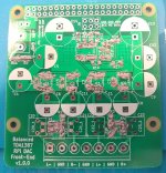
RPI DAC / Front-End v1.0.0
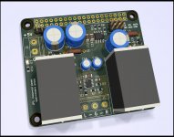
A couple pages back in post #219, I mentioned my next iteration on simple tda1387 DACs: an RPI HAT and/or standalone front-end. Features:
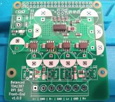
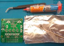
Once again I used my simple stovetop + skillet method of doing the SMD soldering. I included pictures of that process for a little mini-tutorial:
01 - Tools of the trade: Mechanic-brand XG-Z40 solder paste (ebay), precision tweezers, toothpick.
02 - Initial "painting" of solder paste on all solder pads; this isn't pretty, just a first step towards getting initial coverage.
03 - Cleaned up solder paste. What's interesting here is that these photos act as somewhat of a magnifying glass. The solder paste looked pretty neat to my naked eye, but now that I have large hires photos, I can see it's not that neat. Anyway, this is the most time-consuming step. You definitely don't want too much solder paste, as that inevitably results in solder bridges that are a real pain to clean up. I liken this step to painting a wall in your house: the more time you spend on prep, the better the job goes. At a minimum, I try very hard to make sure there's only a very thin coating of paste on IC pin pads; i.e., the smaller and more closely-spaced the pads are, the more care needs to be take that there's not too much solder paste.
04 - Components placed. Pretty easy with the precision tweezers. Just double- and triple-check that the right components and correct values are being placed (rework sucks!).
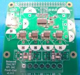
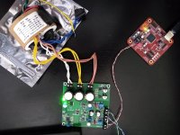
05 - After the "reflow", i.e. after being cooked on the skilled. I basically turn the heat to medium, let it heat up a while. Then I place the PCB on the skillet and crank the heat to max. Now is the fun part: the solder paste will melt, and surface tension pulls it all in neatly, and even tends to square the parts a bit. Once all paste has turned molten, I give it another few seconds, kill the heat, and remove the board from the skillet. After it cools, I do basic sanity checking with the multi-meter. I look for unwanted shorts and continuity where expected. See where I circled pin8 of one of the tda1387 chips? Even though that solder joint looks OK, it was actually fairly dodgy and not giving good continuity to the solder pad. A quick touch-up with the soldering iron fixed it.
(not shown) - Solder all through-hole components. I try to start with the smallest/shortest components, and work up in size.
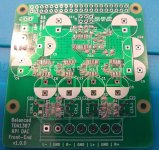
06 - Playing sweet sweet music! Everything worked on the first try. I tested each single-ended pair of outputs individually first. I always use a low power amp and cheap speakers for the first power-on. Once I saw everything was working as expected, I then wired for differential output and moved up to my semi-decent basement amp and speakers. I like to let things like this run continuously for at least 24 hours before doing serious listening. I mainly want to ensure that any potentially marginal solder joints have a chance to show themselves and/or see if the design itself is prone to an early death.
(Actually, on the very first power-on, I had no sound. I was like, what the heck? But then I realized my amp wasn't plugged in!)
A couple pages back in post #219, I mentioned my next iteration on simple tda1387 DACs: an RPI HAT and/or standalone front-end. Features:
- 2x2 tda1387 DAC chips in balanced config (using HC86 to invert I2S DATA signal)
- 5mm pitch screw terminal for 5V power or power from RPI via jumper
- Simple passive I/V or simply omit IV components and have a direct current-output (e.g. for separate I/V board)
- Massive overkill amount of pin5 (5v supply) capacitance
- 2x6 I2S pin header for use as a standalone DAC or front-end
Once again I used my simple stovetop + skillet method of doing the SMD soldering. I included pictures of that process for a little mini-tutorial:
01 - Tools of the trade: Mechanic-brand XG-Z40 solder paste (ebay), precision tweezers, toothpick.
02 - Initial "painting" of solder paste on all solder pads; this isn't pretty, just a first step towards getting initial coverage.
03 - Cleaned up solder paste. What's interesting here is that these photos act as somewhat of a magnifying glass. The solder paste looked pretty neat to my naked eye, but now that I have large hires photos, I can see it's not that neat. Anyway, this is the most time-consuming step. You definitely don't want too much solder paste, as that inevitably results in solder bridges that are a real pain to clean up. I liken this step to painting a wall in your house: the more time you spend on prep, the better the job goes. At a minimum, I try very hard to make sure there's only a very thin coating of paste on IC pin pads; i.e., the smaller and more closely-spaced the pads are, the more care needs to be take that there's not too much solder paste.
04 - Components placed. Pretty easy with the precision tweezers. Just double- and triple-check that the right components and correct values are being placed (rework sucks!).
05 - After the "reflow", i.e. after being cooked on the skilled. I basically turn the heat to medium, let it heat up a while. Then I place the PCB on the skillet and crank the heat to max. Now is the fun part: the solder paste will melt, and surface tension pulls it all in neatly, and even tends to square the parts a bit. Once all paste has turned molten, I give it another few seconds, kill the heat, and remove the board from the skillet. After it cools, I do basic sanity checking with the multi-meter. I look for unwanted shorts and continuity where expected. See where I circled pin8 of one of the tda1387 chips? Even though that solder joint looks OK, it was actually fairly dodgy and not giving good continuity to the solder pad. A quick touch-up with the soldering iron fixed it.
(not shown) - Solder all through-hole components. I try to start with the smallest/shortest components, and work up in size.
06 - Playing sweet sweet music! Everything worked on the first try. I tested each single-ended pair of outputs individually first. I always use a low power amp and cheap speakers for the first power-on. Once I saw everything was working as expected, I then wired for differential output and moved up to my semi-decent basement amp and speakers. I like to let things like this run continuously for at least 24 hours before doing serious listening. I mainly want to ensure that any potentially marginal solder joints have a chance to show themselves and/or see if the design itself is prone to an early death.
(Actually, on the very first power-on, I had no sound. I was like, what the heck? But then I realized my amp wasn't plugged in!)
Attachments

A few updates for those interested in this(these) on-going project(s):
1. I am completely out of single-ended RPI HAT boards. But someone just emailed me asking if I had any left. If there's enough interest, I could order another batch and distribute.
2. The balanced hat/front-end pictured above has been playing for a while. It's "OK". The classic tda1387 "sweetness" I love is there, but my immediate impression is that it's a bit "flat" compared to all the other tda1387 DACs I've heard. IIRC, this is consistent with Abraxalito's observations of passive I/V. The other problem is, it didn't eliminate the subtle hissing I hear when used with my tda8932 amp and office speakers (in fact, it's even more prominent). I originally thought the single transistor active I/V might be to blame, but clearly that's not the case. So now I need to build a real I/V stage for it!
3. What started my love affair was the TDA1387x8 DAC described in this thread. It appears there is now a somewhat upgraded version available, search ebay for "tda1387 8Xse" (example 1, example 2, example 3, example 4. I haven't bought one of these, so can only go by the pictures. But it looks like at least some of the mods/suggestions were incorporated into the newer version. And if nothing else, it's clearly much bigger, so easier to work in!
4. Here's another random ebay find: Philips Little Giant TDA1387 hum decoding (nos mode) (upgrade tda1541) (seller shenglongsi). I placed an order for one of these last night (came to just over $42 with ebay promo code "PREGAME15"). We'll see how it looks in person, but to my untrained eyes, it looks to be one of the most sophisticated tda1387 implementations I've seen outside of this forum. Going by the pics, it looks like it has a complete output stage (I/V, filtering, buffer), and also appears to use LDOs fancier than lm317. I thought it was worth a gamble if nothing else.
A few updates for those interested in this(these) on-going project(s):
1. I am completely out of single-ended RPI HAT boards. But someone just emailed me asking if I had any left. If there's enough interest, I could order another batch and distribute.
I would absolutely buy a few! Would likely be interested in the balanced version as well potentially.
4. Here's another random ebay find: Philips Little Giant TDA1387 hum decoding (nos mode) (upgrade tda1541) (seller shenglongsi). I placed an order for one of these last night (came to just over $42 with ebay promo code "PREGAME15"). We'll see how it looks in person, but to my untrained eyes, it looks to be one of the most sophisticated tda1387 implementations I've seen outside of this forum. Going by the pics, it looks like it has a complete output stage (I/V, filtering, buffer), and also appears to use LDOs fancier than lm317. I thought it was worth a gamble if nothing else.
Those do look promising.... so I just bought one too 😀
Cheers,
Gable
Last edited:
3. What started my love affair was the TDA1387x8 DAC described in this thread. It appears there is now a somewhat upgraded version available, search ebay for "tda1387 8Xse" (example 1, example 2, example 3, example 4. I haven't bought one of these, so can only go by the pictures. But it looks like at least some of the mods/suggestions were incorporated into the newer version. And if nothing else, it's clearly much bigger, so easier to work in!
Very nice find Matt - here's the Taobao link (price looks much cheaper but then it doesn't include shipping) - https://item.taobao.com/item.htm?spm=a230r.1.14.59.653027fbWfRcrf&id=566760076887&ns=1&abbucket=6#detail
I agree - the extra space inside is hugely helpful for modding. I am thinking perhaps I can secure a few lingDAC boards inside. Remember to watch out for the mains safety though, there's no insulation on the tags of the IEC inlet.
4. Here's another random ebay find: Philips Little Giant TDA1387 hum decoding (nos mode) (upgrade tda1541) (seller shenglongsi). I placed an order for one of these last night (came to just over $42 with ebay promo code "PREGAME15"). We'll see how it looks in person, but to my untrained eyes, it looks to be one of the most sophisticated tda1387 implementations I've seen outside of this forum. Going by the pics, it looks like it has a complete output stage (I/V, filtering, buffer), and also appears to use LDOs fancier than lm317. I thought it was worth a gamble if nothing else.
I agree, I've not seen such a sophisticated NOS DAC on sale in PCB form before, and so affordable. The opamps are OP42 for I/V and filtering, he's used MELF resistors and the grounding looks thought out. I haven't been able to figure out what the two square ICs are diagonally opposite the AK4118 are. Presumably regulators by why so many pins?
Very interested to hear how it sounds 😀
Just found the Taobao link : https://item.taobao.com/item.htm?spm=a230r.1.14.45.4e784061q7165A&id=576159460868&ns=1&abbucket=6#detail
Last edited:
4. Here's another random ebay find: Philips Little Giant TDA1387 hum decoding (nos mode) (upgrade tda1541) (seller shenglongsi). I placed an order for one of these last night (came to just over $42 with ebay promo code "PREGAME15"). We'll see how it looks in person, but to my untrained eyes, it looks to be one of the most sophisticated tda1387 implementations I've seen outside of this forum. Going by the pics, it looks like it has a complete output stage (I/V, filtering, buffer), and also appears to use LDOs fancier than lm317. I thought it was worth a gamble if nothing else.
I agree, I've not seen such a sophisticated NOS DAC on sale in PCB form before, and so affordable. The opamps are OP42 for I/V and filtering, he's used MELF resistors and the grounding looks thought out. I haven't been able to figure out what the two square ICs are diagonally opposite the AK4118 are. Presumably regulators by why so many pins?
Very interested to hear how it sounds 😀
Just found the Taobao link : ???TDA1387?????nos??????tda1541?-???
I received this a couple days ago, just now got it up and running. It's SPDIF input (technically I could solder I2S wires directly to the tda1387 pins, but not ready to take a soldering iron to it yet). So I had to find my WaveIO USB to I2S/SPDIF board that I've never used. (I do have a cheap RPI SPDIF HAT on order.) Currently just powering the WaveIO from USB.
The "FD TDA1387nos" board has two 14-16 VAC and one 7-9 VAC power inputs. I'm using a 30VA R-core transformer with two 15V/0.5A secondaries, and two 9V/0.8A secondaries (one of those is taped off).
Everything fired up nicely on the first try! I thought XMOS devices (such as the WaveIO card) required drivers for Windows, but this just worked. Playing via Foobar2000 using ASIO4ALL.
The current setup is far from optimal: over-long cheap USB cable from my PC to the WaveIO card; WaveIO is USB powered (rather than dedicated); really long RCA cables draped across my office from desk to amplifier.
Despite that, my first impression is a definite thumbs-up. It seems very "lively" and "crisp" to me. Perhaps this is what people mean when they refer to dynamics? I need more time with it to say for sure, but this definitely feels like the "cleanest" tda1387 implementation I've heard. Absolutely worth $50. Right now I'm thinking it's worth the time and effort to put into an enclosure and keep as a reference. And then buy another one for study and possible hacking.
I'll try to take some nice hi-res pics later today. But what I received looks exactly like the ebay listing pics. I had to use a flashlight and magnifying glass to read the lids of some of the ICs. In particular:
- The two little square ICs opposite the AK4118 Abraxalito asked about have the following written on them:
Code:PXSO (probably actually PXSQ) TI 821 CL3K G4If I web search for PXSQ and PXQQ, it leads me to the TI regulators TPS7A4700 and TPS7A33, respectively. They are positive and negative regulators, presumably for op-amp power. The pinout matches. (Why so many pins? Most are actually NC.) Spec-wise, those look to be pretty decent (especially considering this board's price).Code:PXQQ TI 631 A2R4 G4 - There's another little 8-pin regulator, between the tda1387 and the two silver electrolytics. This one says:
Web search suggests this is a TI TPS7A49xx. I suspect this is for powering the tda1387. This also looks to be a very solid regulator (again keeping the price in mind).Code:84TI PTJQ - Yet another regulator, ST L78, which is by the power-on LED.
Attachments
- Home
- Source & Line
- Digital Line Level
- tda1387 dac pcb "front end"