Hi Ray,
The package arrived, thank you very much.
The boards look very nice.
Thank you also for facilitating this group-buy and alerting me to it in the first place.
Much appreciated!
Steve.
The package arrived, thank you very much.
The boards look very nice.
Thank you also for facilitating this group-buy and alerting me to it in the first place.
Much appreciated!
Steve.
I've been contacted by a couple of people asking about PCB's for Marcel's DAC - unfortunately there are no boards left from the Group Buy, however, if you guys want to get together I'll be happy to provide you with the information to enable you to buy a small batch of PCBs and I have some spare filter boards available.
For information, an additional batch of 5 PCBs (delivered) will cost you something in the region of $450.
If that's of interest I suggest one of you steps forward and posts to get the ball rolling. Over to you.
For information, an additional batch of 5 PCBs (delivered) will cost you something in the region of $450.
If that's of interest I suggest one of you steps forward and posts to get the ball rolling. Over to you.
If there ever is a group buy on the original PCB that does the PCM to DSD, include me in that. $90 isn't that bad
In 2018, leadbelly attempted to start a group buy for the PCB of the original valve DAC, but he had a minimum order quantity of ten and only six interested members including himself, see Interest for GB for MarcelvdG valve DAC
Well, there might be more interest today in comparison to 2018. I would be in 100% shurely, even though I have the DSD only PCB now. The full version with PCM compatibility would be even nicer for my purposes.
So that's two 😀. I'd even buy two PCBs if it got us to 5, or whatever the minimum needed would be.
HenSch and SonnyMarrow, I don't know if leadbelly and the others are still interested after more than two years, but you could subscribe to the old group buy thread and see what reply you get. The list of people who wanted a board in 2018 is here:
https://www.diyaudio.com/forums/group-buys/313714-gb-marcelvdg-valve-dac-3.html#post5347445
https://www.diyaudio.com/forums/group-buys/313714-gb-marcelvdg-valve-dac-3.html#post5347445
So that's two 😀. I'd even buy two PCBs if it got us to 5, or whatever the minimum needed would be.
If you do decide to go with Marcel's original version I know there are people wanting PCBs for the DSD version - selling yours on might help offset some of the cost for you and help out those guys?
I bumped that thread in hopes those people notice. I suppose I could sell the DSD one, but I wouldn't be opposed to having both. Would those filter boards I bought work with the original version?
Also, are there any pictures of a completed DSD-only build? I can only find pictures of the original.
Also, are there any pictures of a completed DSD-only build? I can only find pictures of the original.
DSD Valve DAC Pictures
I've posted several images of my DSD Valve DAC project previously but here's a link to my album on Imgur;
Valve DAC - Album on Imgur
and an image from the album of the finished project;

Also, are there any pictures of a completed DSD-only build? I can only find pictures of the original.
I've posted several images of my DSD Valve DAC project previously but here's a link to my album on Imgur;
Valve DAC - Album on Imgur
and an image from the album of the finished project;
Last edited:
Ah for some reason I thought that was the full version. I must have have misread that the DSD only version has one less set of tubes. Thanks!
I've posted several images of my DSD Valve DAC project previously but here's a link to my album on Imgur;
and an image from the album of the finished project;
Truly a thing of beauty! Nicely done.
Ah for some reason I thought that was the full version. I must have have misread that the DSD only version has one less set of tubes. Thanks!
The full version has three more valves, an ECC81 that is used as a crystal oscillator and two EF80s that are used as a clock buffer and as a supply voltage regulator for the crystal oscillator. By the way, it is not nearly as pretty as Ray's builds.
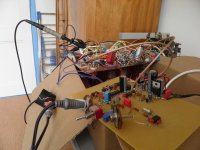
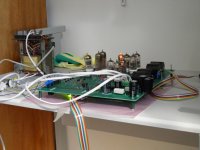
These are a couple of photos of the original valve DAC. The first two show an early experimental set-up that didn't include any of the digital processing yet, it only played back a sigma-delta modulate from a sigma-delta modulator made with some ICs on a piece of perfboard. The third shows the valve DAC main board in the first set-up that actually converted PCM digital to analogue. The fourth and last picture, which was made by Piet Blaas from the NVHR, is the best picture I have of the final DAC.
In this fourth picture, the valve at the bottom of the picture is the ECC81 crystal oscillator, the two above that are the EF80 valves for the clock buffer/voltage regulator, the one on the left is the 85A2 voltage reference and the two groups of three valves above that are the left and right E88CC two-tap RTZ FIRDACs.
In this fourth picture, the valve at the bottom of the picture is the ECC81 crystal oscillator, the two above that are the EF80 valves for the clock buffer/voltage regulator, the one on the left is the 85A2 voltage reference and the two groups of three valves above that are the left and right E88CC two-tap RTZ FIRDACs.
Attachments


Last edited:
Connector P12
Ray's build does not show connector P12 populated. From the KicadTop document I can see that it would connect something to the Mute/DSD circiutry.
Is it a now unnecessary leftover from the original board?
Ray's build does not show connector P12 populated. From the KicadTop document I can see that it would connect something to the Mute/DSD circiutry.
Is it a now unnecessary leftover from the original board?
You have the choice between using U.FL connectors for the clock and data signals and P12 for the MUTE and DSDON signals, or to use the Amanero-style connector P13 (which by mistake was based on obsolete Amanero documentation and may need to have some pins removed, see post #1) for everything.
If you only want to use the Amanero-style connector, P12 and the U.FL connectors are unnecessary, if you don't want to use the Amanero-style connector, P13 is unnecessary. Mind the 0 ohm resistors, as explained in post #1.
If you only want to use the Amanero-style connector, P12 and the U.FL connectors are unnecessary, if you don't want to use the Amanero-style connector, P13 is unnecessary. Mind the 0 ohm resistors, as explained in post #1.
- Home
- Source & Line
- Digital Line Level
- Valve DAC from Linear Audio volume 13