I guess I'm going to do the DSD version. So now I need HQ player or something to convert my output to DSD?
There are various options, HQ Player, Roon, Daphile and JRiver are software players that can do the DSD stuff or there are hardware options such as the AK4137 or CT7302. I only have experience of HQ Player.
Ok I'll look into the hardware options first. I was trying to avoid DSD so I can use the DAC without hassle on Windows. The normal variant with FPGA sounded nice, but the availability of the PCB for the DSD-only variant is too good to pass up.
Last edited:
Do you know roughly how much the normal version would be? I know getting the main PCB made is going to be pricy since it's a single order.
The last time I estimated it, it was just over 1000 euro when you find relatively cheap E88CC valves and don't need the output transformers because you only want to drive balanced inputs. When you do need the output transformers: the Jensen JT-11SSP-7MPC transformers cost $137.46 each and you need one for each channel.
The PCBs I used came from Eurocircuits - I like to sometimes buy things that are not made in China for reasons that are political and are therefore not allowed to be discussed on this forum. The PCB stack-up is actually the default stack-up for Eurocircuits, but still having a single main board manufactured there would now cost 328.74 euro including VAT, or 271.69 euro excluding VAT. The filter board was much cheaper, of the order of 50 euro. Since you are on the other side of the ocean, I guess you don't pay VAT but pay import taxes instead - at least that's what I paid when I bought Jensen transformers.
The FPGA board was another expensive part. It now costs $ 219.30 at Digi-Key (with 0 stock and 12 weeks lead time) and 219.24 euro including or 189 euro excluding VAT at Trenz Electronic in Germany.
The raw-DSD version has no FPGA board, a smaller main PCB, three less valves and simpler reconstruction filters. On the other hand, HQPlayer also costs money, as do Pavel's PCM-to-DSD conversion boards which you could maybe use instead of HQPlayer.
Ok I'll look into the hardware options first.
This hardware solution is based on the AK4137 but you'll probably prefer a USB based solution?
https://www.diyaudio.com/forums/dig...-simple-dsd-src-beaglebone-4.html#post6378889
Last edited:
USB would be convenient, but if it's too much of a pain, I can just use hqplayer. I have my Gamma 3 for general use. If I like the DAC a lot, maybe then I'll pay the premium for the standard variant.
Some good news, 8 of the 9 PCBs have been completed for smd assembly and I'll be arranging to ship them out as soon as I can collect them from my friend's place, hopefully in the next day or two. As you guys have had to wait patiently I'll get them on their way and sort out the final payments to cover the shipping cost afterwards.
The 9th board is waiting on a final part but should follow very soon.
Ray
The 9th board is waiting on a final part but should follow very soon.
Ray
Even more good news! All nine PCBs are now completed with smd soldering and I will be collecting and despatching them tomorrow morning. I'll update with tracking information in due course and will post an updated spreadsheet with the final amounts owing.
Also, the last available bare PCB has been sold to 'SonnyMarrow' and will also be sent tomorrow.
I also hope to collect my second-build PCB tomorrow so I hope to be able to explore alternaite filter stages etc. I am planning an amplifier project with a balanced input so one possibility will be a simple filter with no output transformer - Marcel, do I need to make any changes to the filters if I don't have transformers in that context?
You could use the circuit of post #215, https://www.diyaudio.com/forums/dig...-linear-audio-volume-13-a-22.html#post5872031 , but without the transformer, without R2, without R3 and without C9 and with the midpoint of the two 402 ohm resistors R1 and R4 connected to ground.
If there is a chance that you may have long cables to drive, you could also use the right circuit of post #837, https://www.diyaudio.com/forums/dig...-linear-audio-volume-13-a-84.html#post6328063 , with the transformer, R3 and C9 removed and with C2 and C6 increased to 15 nF each. The capacitors on the main board then have to be 5.1 nF rather than 15 nF.
If there is a chance that you may have long cables to drive, you could also use the right circuit of post #837, https://www.diyaudio.com/forums/dig...-linear-audio-volume-13-a-84.html#post6328063 , with the transformer, R3 and C9 removed and with C2 and C6 increased to 15 nF each. The capacitors on the main board then have to be 5.1 nF rather than 15 nF.
Better Start Watching for the Postman!
All the remaining PCBs were posted this morning. I will sent each recipient a PM with their tracking number.
That all but concludes the group buy; the cells in column 'N' of the spreadsheet are the final payments due to cover the shipping costs and accounting for any adjustments.
Fingers-crossed that all the boards arrive safely...
Ray
Attachments
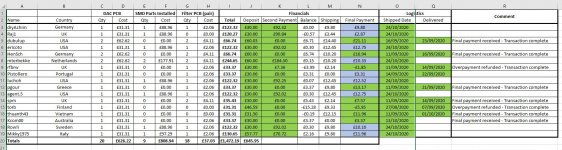
I've sent tracking information and final payment requests.
I think I got everything right but let me know if you think I've made an error.
Cheers
Ray
I think I got everything right but let me know if you think I've made an error.
Cheers
Ray
Thanks!
Thanks Ray for your work with this group buy. And thank your friend too for the help with soldering!
Looking forward to get the PCBs. I will probably take a while before I have time to start construction. But I'm starting to collect things that I need to build the DAC.
I found a suitable R-core transformer with all the voltages one need.
Ordered one, thought maybe interesting for others too.
My plan is to use 6.3V AC for heater, a Neurochrome Maida Regulator for 300V B-, and a Salas UltraBib for 5V.
Marcel, when you write "long cables to drive". 3-4 meter RCA cable, you think that's OK with "Rays Filter PCB" version?
I have 10K input impedance in my active crossover (single-ended inputs). Will be located after the DAC.
Or better solution to remove transformer in DAC, add an input transformer or perhaps neurochrome universal-buffer at active crossover side, and use differential XLR cables?
regards
Micke
Forgot to mention that the packages for the Valve DAC PCBs contain the filter PCBs as well for those who ordered them - don't forget to retrieve them before you discard the packaging!
I have a few spare filter PCBs if anyone needs some down the line.
I have a few spare filter PCBs if anyone needs some down the line.
Thanks Ray for your work with this group buy. And thank your friend too for the help with soldering!
No problem, you're very welcome.
My plan is to use 6.3V AC for heater, a Neurochrome Maida Regulator for 300V B-, and a Salas UltraBib for 5V.
I also use 21st Century Maida reg that uses Tom C's circuit for the B- on my first build - it works well.
For the 5V requirement I use the onboard circuit but substituted one of these (LT3045 version) for the three-legged device;
Voltage Regulator
I run a simple regulator for DC filament supplies.
Marcel, when you write "long cables to drive". 3-4 meter RCA cable, you think that's OK with "Rays Filter PCB" version?
I have 10K input impedance in my active crossover (single-ended inputs). Will be located after the DAC.
Or better solution to remove transformer in DAC, add an input transformer or perhaps neurochrome universal-buffer at active crossover side, and use differential XLR cables?
regards
Micke
Could you use thin 75 ohm coax cable for the RCA connections or does it need to be run-of-the-mill RCA cable?
The cable capacitance is effectively in parallel with the series connection of the last pair of filter capacitors. With the schematic of post #215, there are two 5.1 nF capacitors together giving a capacitance of 2.55 nF. 4 metres of 280 pF/m cheap PVC-insulated RCA cable is 1.12 nF, so almost half the 2.55 nF. 4 metres of 67 pF/m polyethylene-insulated 75 ohm coax cable is only 268 pF.
With the alternative filter topology (post #837 right), the biggest capacitors are on the output side, so the cable capacitance is a smaller percentage of the designed capacitance.
All of this mainly gives response aberrations around 40 kHz, so it will be more noticable to your dog or cat than to you.

- Home
- Source & Line
- Digital Line Level
- Valve DAC from Linear Audio volume 13