DF, I miss your sarcasms from last year. It's good to be frank and straight forward, but it is a fact that you have a quite nasty tone.
If you are so convinced I'm wrong then you must back up your claims.
After I got the idea with the LC thing I stumbled over a colpitt oscillator and it had actually an LC resonator between the oscillator and the comparator. The Q value wasn't as pronounced as in my circuit though. It was claimed to have very low jitter.
http://www.hagtech.com/pdf/hagclockman.pdf
From a theoretical point of view, the LC resonator makes sense, why shouldn't it? A LC resonator creates an equivalent of a "mass" like a pendulum that evens out random jitter. I have also read about jitter reducing tecnology using this principle.
However, my mistake is to just assume that it works without testing. It may be so that the coil etc.. picks up noise from the surroundings and worsens things.
DF96 - I think you are an unhappy individual. You should start meditating or practice yoga, such things can make wonders.
Nowhere does it claim that the LC in the Hagclock reduces jitter. My guess is that they used it as a convenient way of getting an AC signal with zero DC to feed into the output chip. If you bothered to do a calculation you would discover that their LC has a loaded Q around 1-1.5. Typical small inductors have a Q around 100, so even the unloaded Q would be totally inadequate to reduce jitter from a crystal oscillator. A crystal has Q in the region 10k-100k or thereabouts. To reduce jitter you would need as a minimum a filter containing a similar or better crystal; even that would only make a small difference.
As I said, you need to read a textbook on oscillator noise theory.
As I said, you need to read a textbook on oscillator noise theory.
Jitter manifest itself as distorsion and not as a "timing" error. Reproducing a sample in the wrong time, skews the represented, and intended, waveform.
I think there have been tests that prove human detection of (was it?) 100 ps.
//
Jitter is most certainly a "timing error". What else do you call a waveform that is moving back and forth against a reference window.
That error when converted back to an analog voltage causes inter-modulation which is in fact a distortion.
Show me a accredited DBT test where someone could discern 100ps of jitter on a 96K or 48K digital audio signal?
P.S. "Accredited" means and AES, IEEE, EBU, SMPTE, or university documented test. Anything from an audiophile magazine is not accredited!
Last edited:
I said "manifest" - do you understand what I mean by that?
I did reserve myself - the figure was as I recollect it. It might be wrong.
20ps-500ns : http://www.nanophon.com/audio/jitter92.pdf
//
I did reserve myself - the figure was as I recollect it. It might be wrong.
20ps-500ns : http://www.nanophon.com/audio/jitter92.pdf
//
Last edited:
I said "manifest" - do you understand what I mean by that?
I did reserve myself - the figure was as I recollect it. It might be wrong.
20ps-500ns : http://www.nanophon.com/audio/jitter92.pdf
//
The graphs show 20ns examples, not 20ps. Big difference.
Alright, game on 😀
Now, everyone worries about jitter in the audio band, but you can also have jitter at higher frequencies. For example, the SPDIF receiver VCO in (say) CS8416 is just a crummy high phase noise VCO, not a classy and refined VCXO... Depending on PLL bandwidth, it will copy the jitter from the source below something like 30k, and add its own phase noise above. And its noise floor isn't that low.
Also, stick a HDMI cable in your big HT receiver. Okay, now you got a HDMI receiver chip outputting audio MCLK. A tiny point of detail : usually, audio MCLK is generated from some high frequency, high-jitter clock which is recovered via PLL from the HDMI source... it is synced to video and not a multiple of audio sample rate... which means MCLK is generated by using an Fractional-N divider. This means if the master video clock is 300 Mhz and you need 22.579 then you got a counter on the 300 MHz clock which divides by 13 most of the times, and occasionally by 14, so you get your 22.579 on average at the output... of course some cycles are gonna be a little longer than others, but who cares, right ?
"In the Feb 2009 edition of the Hi-fi News magazine Paul Miller measured the following jitter results for a few A/V amplifiers:
Denon AVR-3803A
---------------
SPDIF: 560psec
HDMI: 3700psec
Onkyo TX-NR906
---------------
SPDIF: 470psec
HDMI: 3860psec
Pioneer SC-LX81
---------------
SPDIF: 37psec
HDMI: 50psec
Yamaha RX-V3900
---------------
SPDIF: 183psec
HDMI: 7660psec"
Now, if you use a good old NonOS PCM63 then you only got to worry about jitter in the audio band. However, what if you use, say... a sigma delta DAC? Then you got to worry about HF jitter too.
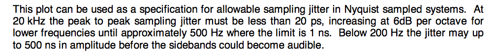
Time for a little simulation. I wanted to try a 1-bit DAC first, but didn't want to bother with finding a working software sigma delta encoder, so I used a software DSD64 encoder instead. The test signal is a 11025 Hz sine wave. I loaded the bits into Python and simulated a direct, 1-bit DAC subjected to simulated amounts of jitter. See attached FFT.
This neatly explains why no-one uses 1-bit DACs anymore* : a little bit of wideband jitter (like 100ps) utterly destroys an easily measurable characteristic (ie, SNR).
* = besides "the best DAC is no DAC" topic of course
Hence, multibit sigma delta DACs became fashionable. Sensitivity to jitter in the audio band is the same, but sensitivity to HF jitter is inversely proportional to the derivative of the DAC output, which is to say, the number of modulator levels.
Another way to say it is that HF jitter folds HF modulator noise back into the audio band, so a DAC with much less modulator noise (ie, multibit) will be much less vulnerable.
Simulation results are coming...
Now, everyone worries about jitter in the audio band, but you can also have jitter at higher frequencies. For example, the SPDIF receiver VCO in (say) CS8416 is just a crummy high phase noise VCO, not a classy and refined VCXO... Depending on PLL bandwidth, it will copy the jitter from the source below something like 30k, and add its own phase noise above. And its noise floor isn't that low.
Also, stick a HDMI cable in your big HT receiver. Okay, now you got a HDMI receiver chip outputting audio MCLK. A tiny point of detail : usually, audio MCLK is generated from some high frequency, high-jitter clock which is recovered via PLL from the HDMI source... it is synced to video and not a multiple of audio sample rate... which means MCLK is generated by using an Fractional-N divider. This means if the master video clock is 300 Mhz and you need 22.579 then you got a counter on the 300 MHz clock which divides by 13 most of the times, and occasionally by 14, so you get your 22.579 on average at the output... of course some cycles are gonna be a little longer than others, but who cares, right ?
"In the Feb 2009 edition of the Hi-fi News magazine Paul Miller measured the following jitter results for a few A/V amplifiers:
Denon AVR-3803A
---------------
SPDIF: 560psec
HDMI: 3700psec
Onkyo TX-NR906
---------------
SPDIF: 470psec
HDMI: 3860psec
Pioneer SC-LX81
---------------
SPDIF: 37psec
HDMI: 50psec
Yamaha RX-V3900
---------------
SPDIF: 183psec
HDMI: 7660psec"
Now, if you use a good old NonOS PCM63 then you only got to worry about jitter in the audio band. However, what if you use, say... a sigma delta DAC? Then you got to worry about HF jitter too.
Time for a little simulation. I wanted to try a 1-bit DAC first, but didn't want to bother with finding a working software sigma delta encoder, so I used a software DSD64 encoder instead. The test signal is a 11025 Hz sine wave. I loaded the bits into Python and simulated a direct, 1-bit DAC subjected to simulated amounts of jitter. See attached FFT.
This neatly explains why no-one uses 1-bit DACs anymore* : a little bit of wideband jitter (like 100ps) utterly destroys an easily measurable characteristic (ie, SNR).
* = besides "the best DAC is no DAC" topic of course
Hence, multibit sigma delta DACs became fashionable. Sensitivity to jitter in the audio band is the same, but sensitivity to HF jitter is inversely proportional to the derivative of the DAC output, which is to say, the number of modulator levels.
Another way to say it is that HF jitter folds HF modulator noise back into the audio band, so a DAC with much less modulator noise (ie, multibit) will be much less vulnerable.
Simulation results are coming...
Attachments
HDMI is a new set of worms!
First audio with video always has a video locked audio sample rate. Division is integer. It has to in order to be muxed with the video stream. That is the reason television digital audio is 48K and multiples thereof where as CD is 44.1K and multiples. The only exception was Laser Disk digital audio track at 44.1k as this was just another RF carrier on the disk and really had no timing clock relation to the video.
One of the problems with HDMI is that the audio is not a continuous stream. It is sent as packets in between horizontal lines in the HANC space. This is a user data area that is left over form the CRT days and was used as horizontal blanking.
So the incoming 48K (or higher) audio is written into dual port RAM and then written out at the video pixel clock. This time compressed the audio to fit in the HANC space. On playback or upon decoding, the process is reversed. It is this function along with the necessary divider chain that causes increased jitter in HDMI interfaces
Note that HDSDI in the broadcast industry has the same issues as HDMI borrowed the technology from HDSDI.
Last edited:
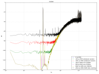
Now, how to simulate a jittery multibit DAC ?
It turns out my DSD encoder supports higher sample rates, so I simply multiplied the DSD sample rate by N, then converted it back into 2.8224 MHz floating point PCM, which gave me the multibit samples I wanted. It isn't completely realistic, but it's the best I got short of a software multibit modulator in source code form. So, caveat emptor. I put a "8-level multibit" legend, but its performance should be quite a bit better than that.
As expected, sensitivity to HF jitter is a lot lower, and SNR stays up to modern standards with a little bit of HF jitter. However, sensitivity to audio-band jitter is exactly the same.
Take-home points :
- When talking about audibility of jitter, you got to consider the type of jitter and its frequency.
- HF jitter components will fold back modulator noise into the audio band and raise the noise floor (this may be signal level dependent also).
- LF jitter components will create intermodulation-like frequencies which may be masked or not...
And IMO, since it's unconfirmed wether it's audible or not, and I suspect it is, there is really no excuse for more than 50-100ps jitter (integrated say from 10Hz and up) since WM8805 is available and does the job just fine, any commercial gear which uses CS8416 or DIR9001 just to save a few bucks, really, come on.
I mean, it's not a super expensive tweak of dubious value like a huge transformer or a machined chassis...
Attachments
This neatly explains why no-one uses 1-bit DACs anymore* : a little bit of wideband jitter (like 100ps) utterly destroys an easily measurable characteristic (ie, SNR).
Hi peufeu - don't overlook that some manufacturers (AKM and Wolfson just to mention two) minimize the issue through using switched-capacitor DACs and output filters. Its the ones that allow off-chip opamps (TI and ADI I'm looking at you) that are going to be most susceptible to jitter. Not that on-chip op-amps don't introduce their own weaknesses....
In the days of 'Bitstream' there was the TDA1547 which had both a S-C 1bit DAC and on-chip opamps (allegedly something similar to 5532).
Thanks a lot for sharing those very illuminating sim results 😀
Last edited:
So that is the noise aspect of jitter in different DAC topologies - interesting! But SNR, is it really critical in the listening situation? How about distorsion?
//
//
SNR if its at a static level doesn't matter too much, what's important for SQ is that the SNR shouldn't change dynamically in a manner correlated with the signal.
SNR if its at a static level doesn't matter too much, what's important for SQ is that the SNR shouldn't change dynamically in a manner correlated with the signal.
Good.
//
Hi peufeu - don't overlook that some manufacturers (AKM and Wolfson just to mention two) minimize the issue through using switched-capacitor DACs
Yeah, charge transfer DACs are supposed to be a lot less jitter-sensitive... I don't know if WM8840 uses this style or the more classic current DACs, couldn't find any info in the datasheet.
So that is the noise aspect of jitter in different DAC topologies - interesting! But SNR, is it really critical in the listening situation? How about distorsion?
//
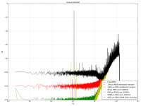
Well, when you FFT a signal, you usually get peaks (harmonic distortion, intermodulation, jitter peaks, etc) and then a noise floor.
The latter is misleading, though. It looks flat and harmless enough, maybe even white noise! Here are several signals whose FFT spectra look rather identical, as you can see the signals are very different, one is harmless white noise, but the others are not, and the last one is even a log frequency sweep !
So, don't trust your noise floor. I's on my todo list to make some measurements on that... someday...
Attachments
I suppose it has to do with the FFT length? A lot will also look like noise if it is averaged over a long enough period.
//
//
As jcx often points out, FFTs don't intrinsically average in that the transform as a whole (real and imaginary) is reversible. However when you look at a pure magnitude plot, half the data's been already neglected (phase). FFTs are a rather poor tool for examining noise.
One question on the spidif output...I often see the isolation transformer (coaxial) and understand what its used for. However how will the transformer impact the jitter/quality of the spidif signal...anyone knows ?
I suppose it has to do with the FFT length? A lot will also look like noise if it is averaged over a long enough period.
For noise, FFT shows power (or amplitude/phase) in each frequency bin, averaged over FFT length. This is why FFT is amazing, since it allows to examine periodic, repeating signals with great precision while rejecting noise from the display.
FFT only reports one value of (phase,amplitude) for each frequency over its length. So, if the signal's phase and amplitude vary, either it does so in a way that maps well to a meaningful visual representation... or it does not.
Anyway. Other measurements (like noise power vs DC offset to check for noise floor modulation, or simply looking at it on a scope) are more useful for noise.
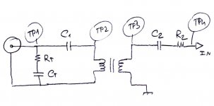
One question on the spidif output...I often see the isolation transformer (coaxial) and understand what its used for. However how will the transformer impact the jitter/quality of the spidif signal...anyone knows ?
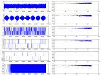
Theory is simple : a transformer is a bandpass system, so it introduces phase shift and amplitude attenuation (see measurement of 3 transformers, curve 5). Therefore it distorts the waveform. LF highpass effects add LF jitter ; HF attenuation slows down edges and also adds jitter.
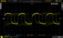
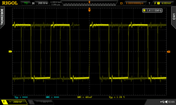
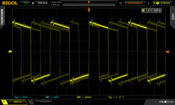
Using a simple matching circuit (first attached image) some of this can be corrected. However, theory breaks down when you realize every SPDIF source has a different output circuit. In practice, it has to be fine-tuned to the source while looking at the scope (see scope shots) as the value of CT should be identical to the series capacitor in the source...
Optical is much simpler ! (and much better isolated)
Attachments

- Status
- Not open for further replies.
- Home
- Source & Line
- Digital Line Level
- S/PDIF and PLL