Two corrections: some leftover components removed and ferrite bead-C filter added for the +5Vraw domain to reduce crosstalk from +5Vraw to other domains.
Looks very nice!
A couple of questions:
How does it sound?
Why do you use an inverter (u20) in front of the two ex-or gates that makes the clock and clockn? Just as a buffer?
Why do you use so much active filtering after the main DAC? Is it very noisy without or with just a passive filter. I, personally, would avoid opamps at that point, as I believe they are performing poorly when exposed to high amounts of HF.
Ultimately I would suggest using 74AUC1G instead of 74LVC and then use LiFePo4 batteries as PS.
Still a very clever design, congrats MarcelvdG
Looks very nice!
A couple of questions:
How does it sound?
The version that I actually built (the PCM version with the FPGA module and SRC4392) sounds quite neutral to me. I haven't listened to it much, though. I've mainly used it to test alternative configuration files for the FPGA of my valve DAC.
Why do you use an inverter (u20) in front of the two ex-or gates that makes the clock and clockn? Just as a buffer?
Buffer and level shifter, the incoming clock will typically have 3.3 V high level rather than 5 V. It is not very nice as a level shifter, though, because it will draw some overlap current out of the 5 V supply that depends on the high level of the incoming signal.
Why do you use so much active filtering after the main DAC? Is it very noisy without or with just a passive filter.
In the original circuit, I used a filter of a slightly higher order than the order of the sigma-delta, thinking that then at least the out-of-band noise spectrum would go down immediately above the signal band. This was a mistake, though, because just above the frequency of the highest notch in the noise transfer function, the quantization noise goes up much faster than with 20 n dB/decade where n is the order of the sigma-delta.
Measuring the out-of-band quantization noise at the output of each filter stage, I found I didn't win much with the last stage (due to its high Q the noise was actually amplified), so I just cut it out for this version. As mentioned, the component values of the filter need an update.
Of course you can replace the active filter with a passive LC filter if you like. I also used an LC filter for my valve DAC, but in this case I wanted to build something compact for a change.
I, personally, would avoid opamps at that point, as I believe they are performing poorly when exposed to high amounts of HF.
Hence the two capacitors to ground before going to the first op-amp (for the right channel: C58, C59, C78 and C79), and the use of FET op-amps with a relatively large slew-rate-to-gain-bandwidth-product ratio (that is, relatively large input stage clipping level).
Ultimately I would suggest using 74AUC1G instead of 74LVC and then use LiFePo4 batteries as PS.
Features I rather like in the 74AHC series are the 5 V voltage handling and the fact that there are several matching gates on the same chip. For example, when U22B and U22D in the right channel DAC match, the fact that their high and low output resistances are unequal will only cause a common-mode error, because whenever one produces a pulse the other doesn't. Then again, the SN74AUC2G series also has matching pairs of gates.
Still a very clever design, congrats MarcelvdG
Thank you.
@ MarcelvdG
Thanks for educative piece (for Me). And innovative approach.
Is it say, master clock, have to be 4x higher than BCK in Your design? I think You mention something about this?
(Sorry but I am not spend much time with the sch.)
cheers
No, not for this version. This one only requires 1 times the bit clock but the bit clock must be quite clean (low jitter).
A clock-synchronous RTZ circuit according to post 2223 would require a clock at eight times the bit clock. JohnW apparently knows a way to make a clock-synchronous version that requires only four times the bit clock, but I don't see how you can do that without some data-dependent current being drawn.
Last edited:
Why not use master clock in stead of bitclock? It should be cleaner , jitter wise , right?No, not for this version. This one only requires 1 times the bit clock but the bit clock must be quite clean (low jitter).
A clock-synchronous RTZ circuit according to post 2223 would require a clock at eight times the bit clock. JohnW apparently knows a way to make a clock-synchronous version that requires only four times the bit clock, but I don't see how you can do that without some data-dependent current being drawn.
So AUC2G for the gates , but AUC1G for the flip flops, as 74AUC2G74 does not exist.Features I rather like in the 74AHC series are the 5 V voltage handling and the fact that there are several matching gates on the same chip. For example, when U22B and U22D in the right channel DAC match, the fact that their high and low output resistances are unequal will only cause a common-mode error, because whenever one produces a pulse the other doesn't. Then again, the SN74AUC2G series also has matching pairs of gates.
Thank you.

Why not use master clock in stead of bitclock? It should be cleaner , jitter wise , right?
Good point. It means that you will play back each DSD64 sample eight times in a row (assuming a 22.5792 MHz master clock), but that should not be a problem.
The only potential problem is the timing relation between the master clock and the data transitions. Does anyone specify what it is, so you can avoid set-up and hold time violations? If not, you would have to clock in the data with a very fast flip-flop running on the bitclock, sample its output with a very fast flip-flop running on the master clock and just hope that nothing gets metastable.
Last edited:
So AUC2G for the gates , but AUC1G for the flip flops, as 74AUC2G74 does not exist.
Mind you, the flip-flops in the actual RTZ circuit should not be too fast. Their delay at least has to be as large as the mismatch between the delays from the two inputs of the NOR or AND gate plus the mismatch in delays between the two EXOR gates and at most as large as the time that their clock is high minus the mismatch between the delays from the two inputs of the NOR or AND gate minus the mismatch in delays between the two EXOR gates. See also post 2182.
Hi all,
I could probably find this myself by looking through all 2247 posts, but out of sheer laziness I'll just ask it:
Some of the circuits in this NoDAC thread use relays for the mute function, but the Signalyst DSC2.something uses an electronic switch. Does an electromechanical relay for the mute work or is it too slow to prevent thumps and clicks?
Hi all,
I could probably find this myself by looking through all 2247 posts, but out of sheer laziness I'll just ask it:
Some of the circuits in this NoDAC thread use relays for the mute function, but the Signalyst DSC2.something uses an electronic switch. Does an electromechanical relay for the mute work or is it too slow to prevent thumps and clicks?
Well, I tried and found out it didn't work, way too slow indeed. Tried a small signal relay.
Btw the search isn't easy in these threads.
Coffee second
Hi again ...
... just a comment on this and - I know - a bit off-topic, but nevertheless ... Some time ago - when there was some talk about a new diyaudio software "backbone" - I suggested adding a feature to the Subscribed Thread functionality which was to allow for adding notes to each subscribed thread. In this way one could add notes about particularly interesting posts - or thoughts/ideas related to the thread in question - directly associated with the thread and thus easy to find again when one needed to go back to some bit of information remembered from "somewhere previously".
Although I am actually grateful for all the information shared and available here on diyaudio I sometimes find it to be a challenge to remember where I read "something" - and IMHO it would be feasible if somehow it was possible to add comments in relation to a specific thread so as to assist my memory ...
Well, you triggered my thoughts mterbekke ;-) .... and with these words end of off-topic for now ...
Cheers,
Jesper
Btw the search isn't easy in these threads.
... just a comment on this and - I know - a bit off-topic, but nevertheless ... Some time ago - when there was some talk about a new diyaudio software "backbone" - I suggested adding a feature to the Subscribed Thread functionality which was to allow for adding notes to each subscribed thread. In this way one could add notes about particularly interesting posts - or thoughts/ideas related to the thread in question - directly associated with the thread and thus easy to find again when one needed to go back to some bit of information remembered from "somewhere previously".
Although I am actually grateful for all the information shared and available here on diyaudio I sometimes find it to be a challenge to remember where I read "something" - and IMHO it would be feasible if somehow it was possible to add comments in relation to a specific thread so as to assist my memory ...
Well, you triggered my thoughts mterbekke ;-) .... and with these words end of off-topic for now ...
Cheers,
Jesper
Hi again ...
I suggested adding a feature to the Subscribed Thread functionality which was to allow for adding notes to each subscribed thread".
I sometimes find it to be a challenge to remember where I read "something" - and IMHO it would be feasible if somehow it was possible to add comments in relation to a specific thread so as to assist my memory ...
Cheers,
Jesper
That's a great idea Jesper, I also think it should be improved upon to keep access to relevant info on mega threads like these. Also: searching is possible on the pc but somehow not on my phone.
Btw Jesper, I still owe you some answers a few pages back. When time permits I'll have s go at them but one I remember is the excessive lf spikes. It is because of bad wiring picking up all sorts of hum etc.
Have a good one!
Hi all,
I could probably find this myself by looking through all 2247 posts, but out of sheer laziness I'll just ask it:
Some of the circuits in this NoDAC thread use relays for the mute function, but the Signalyst DSC2.something uses an electronic switch. Does an electromechanical relay for the mute work or is it too slow to prevent thumps and clicks?
I tried a few circuits for mute-dad-change sample rate etc. (I needed -enable to turn off discrete dad modules when R2R I2S modules are operate, and opposite when DSD pesent)... And it seems that is a n issue with amanero soft. Because always it is too fast with un-mute and simultaneously going into 2 datas changing SR and/or dad/i2S... That is why many users do some delay for un-mute. To pass all other "clicks". Or additional arduino re-mute. Also it is not easy to for instance get the SR indication infoes with simpile decode...
...
I think that could be corrected with code. A few lines to add for delay to un-mute after all changes?
...
I don't know about other interfaces I can check with new xmos model.
mute time
I'm sure the necessary mute time depends on your setup. If your interface is Amanero, your software is also relevant to the mute time. Even both the interface and software are the same, the amplitude of the input signal and OSR can be variables. In my setup where PCM to DSD is hardware implementation, required mute time is predictable. You are free from pop noise if you have 0.1second mute time as long as no change from 44k family to 48k. If it occurs, 0.5second is mandatory for secure operation because not selected oscillator is usually disabled. Enabling another oscillator, waiting for stable operation and PLL lock take some additional time.
You need to clear buffer memory in the oversampling filter to avoid the unexpected operation of DSM. OS filter usually has 1k taps for FIR. It takes 10milisecond in 96kHz sampling(1000*10microsecond) to replace 1k words with zero. 90milisecond is enough for DSM to catch up with a new frequency. That's why 0.1second mute time can guarantee no pop switching. Familly change needs additional 0.4second. An onboard oscillator is mandatory to interface with Rpi, where no system clock available and BCK is jittery. The onboard Xtal based oscillator can recover very clean system clock from LRCK which is jitter-free even in Rpi(an easy and effective way to interface with Rpi). So, I recommend built-in two Xtal based oscillators for versatile use even if it has some startup time.
Thanks all, that's precisely the information I needed. Is it sufficient to just extend the MUTE pulse, or should the (MUTE or not DSDON) pulse be extended?
Hi Marcel. I think ppy's DSC2 projects have muting well-sorted, maybe ask about it on that thread. He keeps his projects in the open so I don't imagine he'll be anything but helpful.
@mterbekke:
It is fine ... no worries ;-) As I wrote a couple of pages back I am currently deep in another project so I am just ever so slightly following this (interesting) thread. But I'd like to hear your feedback in due time - when suitable for you.
Cheers,
Jesper
Btw Jesper, I still owe you some answers a few pages back. When time permits I'll have s go at them but one I remember is the excessive lf spikes. It is because of bad wiring picking up all sorts of hum etc.
It is fine ... no worries ;-) As I wrote a couple of pages back I am currently deep in another project so I am just ever so slightly following this (interesting) thread. But I'd like to hear your feedback in due time - when suitable for you.
Cheers,
Jesper
success
Hi, all. I have managed to achieve a successful result in my noDAC project after a two-month trial. As the theory suggests, 1bitDSM(DSD) has promising potential indeed.
The detail is here.
My no DAC project. FPGA and transistors.
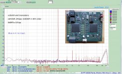
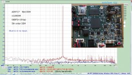
The 1st pic is 1bitDSM with x64OSR in 8th order. The 2nd is my DIYed 5bitDSM(AD9717). 1bitDSM is superior to 5bitDSM.
Hi, all. I have managed to achieve a successful result in my noDAC project after a two-month trial.
As the theory suggests, 1bitDSM(DSD) has promising potential indeed.The detail is here.
My no DAC project. FPGA and transistors.
The 1st pic is 1bitDSM with x64OSR in 8th order. The 2nd is my DIYed 5bitDSM(AD9717). 1bitDSM is superior to 5bitDSM.
Attachments
HI!
all i have new design, the sample, please see this link: STAR Pure DSD DAC-Signalyst New
thank you very much!
all i have new design, the sample, please see this link: STAR Pure DSD DAC-Signalyst New
thank you very much!
I've been contacted by a DIY Audio member who is looking to build a no-DAC based on one of the PCBs I produced a few years back.
The PCB in question is the one that I made a mistake on and requires a simple correction, here's the link to the relevant post;
https://www.diyaudio.com/forums/digital-line-level/273474-dac-dac-110.html#post4653927
Unfortunately, when Photobucket got greedy my account was closed and I lost the images that were linked in the post. Would anyone have copies?
Greetings Ray,
I do not have images, but I have one of the boards you mention. It is populated and not in use. If I recall correctly, the output was a bit low to drive my other components. I have no plans for it and am happy to send it back to you or to whomever might want to work with it. PM if I can be of assistance.
Frank
PS My current project incorporates the latest version of the JLsounds I2S board (version 3), which was a pleasant discovery from my NO DAC trials.
- Home
- Source & Line
- Digital Line Level
- The Best DAC is no DAC