My mind was not right
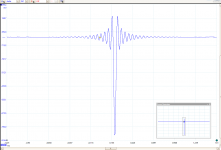
Here are both channels.
1 non-inverted sample pulse.
Channels not in "sync" and inverted.
BTW: I read here that my measurements are "not" correct according til Søren.
http://www.diyaudio.com/forums/vend...magnitude-24-bit-384-khz-272.html#post4332606
I will check my other equipment. Running RPI2 via USB to a gustard U12 (usb-i2s) lvds mode to the dam.
Will test with spdif also.
I'd hazard a guess that the time delay between channels is due to your picoscope, not the DAM.
We seem to have a polarity inversion bug in the volume control...
V+00 polarity is correct
V-01 polarity is inverted
V-02 polarity is correct
V-03 polarity is correct
etc, etc, etc, etc...
V-18 polarity is correct
V-19 polarity is correct
V-20 polarity is correct
V-21 polarity is inverted
V-22 polarity is correct
V-23 polarity is correct
etc, etc, etc, etc...
V-40 polarity is correct
V-41 polarity is inverted
V-42 polarity is correct
V-43 polarity is correct
etc, etc, etc, etc...
V-60 polarity is correct
V-61 polarity is inverted
V-62 polarity is correct
etc, etc, etc, etc...
So volume settings V-01, V-21, V-41, V-61 and I'm guessing V-81 invert polarity cf other volume settings.
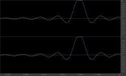
This shows V-40, V-41, V-42. V-41 is clearly inverted and is also at a distinctly lower amplitude.

The capture is about 1.5dB hotter than than it should be, due to running out of attenuation on the ADC:
V-40 = -38.79dB true peak level
V-41 = -41.75dB true peak level <<<< should be approx. 39.80dB
V-42 = -40.82dB true peak level
I'd noticed the volume control had strange steps in a couple of spots, and if this is anything to go by these are the points at which it happens.
I guess depending on how you look at it could be considered a "feature" allowing on the fly polarity inversion...
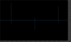
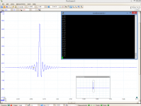
BTW I don't see any timing difference between impulses here. Attached is a clipped impulse at 0dBFS, overloading my soundcard - but no timing difference evident.
V+00 polarity is correct
V-01 polarity is inverted
V-02 polarity is correct
V-03 polarity is correct
etc, etc, etc, etc...
V-18 polarity is correct
V-19 polarity is correct
V-20 polarity is correct
V-21 polarity is inverted
V-22 polarity is correct
V-23 polarity is correct
etc, etc, etc, etc...
V-40 polarity is correct
V-41 polarity is inverted
V-42 polarity is correct
V-43 polarity is correct
etc, etc, etc, etc...
V-60 polarity is correct
V-61 polarity is inverted
V-62 polarity is correct
etc, etc, etc, etc...
So volume settings V-01, V-21, V-41, V-61 and I'm guessing V-81 invert polarity cf other volume settings.
This shows V-40, V-41, V-42. V-41 is clearly inverted and is also at a distinctly lower amplitude.
The capture is about 1.5dB hotter than than it should be, due to running out of attenuation on the ADC:
V-40 = -38.79dB true peak level
V-41 = -41.75dB true peak level <<<< should be approx. 39.80dB
V-42 = -40.82dB true peak level
I'd noticed the volume control had strange steps in a couple of spots, and if this is anything to go by these are the points at which it happens.
I guess depending on how you look at it could be considered a "feature" allowing on the fly polarity inversion...
BTW I don't see any timing difference between impulses here. Attached is a clipped impulse at 0dBFS, overloading my soundcard - but no timing difference evident.
Attachments
Last edited:
Thought I might take a look at the interpolated FIR tool in MATLAB to see if it did anything worthwhile seeing zfe mentioned IFIR's earlier....
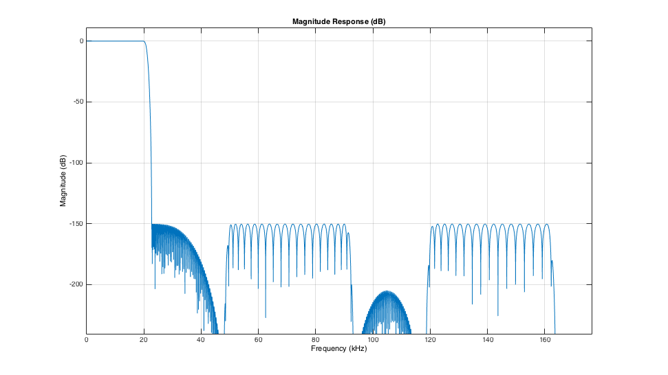
Not sure if the "hole" in the response around 44.1kHz is doing anything useful. Would need to check the outputs to see, and that won't happen today.
I get the feeling with this filter that it needs a bit of extra gain vs the brick wall filters. It may just be a little bit quieter.
This is a second iteration and I've juggled the settings a little to get decent stop band attenuation, reasonable passband ripple and keep the filter short enough to fit into 1016 taps.
No claims it sounds better than anything else, it might even be worse
Attachments

Last edited:
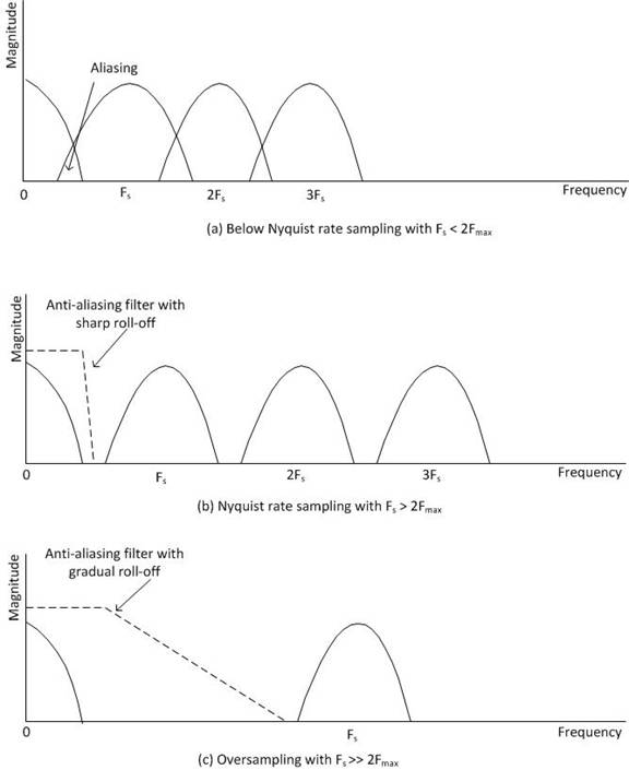
Content within the audio band mirrors around nyquist, and as the rate of oversampling the number of images increases. At x1 you have the original audio + 1 mirror image, at X8 you have the original audio + 15 mirror images.
I believe its not true. Sampled signal has in theory infinite number of mirrors around every multiple of nyquist frequency.
Oversampled signal has also infinite audio band mirrors but around new sampling frequecny which is multiplier of oversampling degree and orginal nyquist freq.
Regards,
Marek
Thought I might take a look at the interpolated FIR tool in MATLAB to see if it did anything worthwhile seeing zfe mentioned IFIR's earlier....
Did you use the "advanced" setting from Matlab? it allows matched Filters like that:

(Taken from P. 582 Digital Signal Processing, S.K. Mkitra)
Theoretically all what you did up to now is a subset of IFIR, but of cause you have for the ususal FIRs a greater variaty of design tools than just that Matlab thing for IFIR.
Did you use the "advanced" setting from Matlab? it allows matched Filters like that:
View attachment 484386
(Taken from P. 582 Digital Signal Processing, S.K. Mkitra)
Theoretically all what you did up to now is a subset of IFIR, but of cause you have for the ususal FIRs a greater variaty of design tools than just that Matlab thing for IFIR.
I have the peasant home edition. No advanced tab that I can see.
I'm pretty much burnt out on doing filters. TBH I can't hear any advantage and I can't identify what is gained by shaping the response in the stop band. Much of the theory is targeted to specific purposes in telecommunications where there is good reason to target specific frequencies.
It seems to me that we are starting to get into the search for novelty for the sake of novelty.
So if you guys want to pick up the baton and push forward more power to you...
But i've spent virtually all my spare time over the last 4 months focused on filters and it's time to move on...
Really nice find and yes this has to be a volume bug or a featureWe seem to have a polarity inversion bug in the volume control...
V+00 polarity is correct
V-01 polarity is inverted
V-02 polarity is correct
V-03 polarity is correct
etc, etc, etc, etc...
V-18 polarity is correct
V-19 polarity is correct
V-20 polarity is correct
V-21 polarity is inverted
V-22 polarity is correct
V-23 polarity is correct
etc, etc, etc, etc...
V-40 polarity is correct
V-41 polarity is inverted
V-42 polarity is correct
V-43 polarity is correct
etc, etc, etc, etc...
V-60 polarity is correct
V-61 polarity is inverted
V-62 polarity is correct
etc, etc, etc, etc...
So volume settings V-01, V-21, V-41, V-61 and I'm guessing V-81 invert polarity cf other volume settings.
This shows V-40, V-41, V-42. V-41 is clearly inverted and is also at a distinctly lower amplitude.
....
In that case it should be fairly simple (I guess) for Soren to implement a phase shift command in the dam when releasing the next firmware?
This is the measured impulse from your latest filter.
Pulse 1 sample.
1. V=00
2. V=-01
Since my Gustard probably invert phase (I read something about it) my measurements are the opposite of what is normal
BTW: The reason why I posted this impulse measurements in this thread was initially because of measuring the filters themself...
Attachments
Cool. Good to have an independent confirmation as I always have the though in the back of my mind that it's a fault in my setup.This is the measured impulse from your latest filter.
Pulse 1 sample.
1. V=00
2. V=-01
Next I will do some listening between V0 and V-01 ? To see if I can hear the difference ?
I will of course notice a big difference. But I guess not knowing which volume setting / phase would make that more difficult
Blind listening is a bitch and very useful
Of course I do not know how my speakers (or amp) is with this issue either...
I will of course notice a big difference. But I guess not knowing which volume setting / phase would make that more difficult
Blind listening is a bitch and very useful
Of course I do not know how my speakers (or amp) is with this issue either...
But i've spent virtually all my spare time over the last 4 months focused on filters and it's time to move on...
Correct! Your last filters sound excellent.
The next step would be more taps and that's up to Soren.
I have the peasant home edition. No advanced tab that I can see.
Interpolated FIR filter from filter specification - MATLAB ifir
[...] = ifir(...,str) uses the string specified in str to choose the algorithm level of optimization used. Possible values for str are 'simple', 'intermediate' (default) or 'advanced'. str provides for a tradeoff between design speed and filter order optimization. The 'advanced' option can result in substantial filter order reduction, especially for g(z).
The aim is to get the same performance with less filter tabs.TBH I can't hear any advantage and I can't identify what is gained by shaping the response in the stop band.
But i've spent virtually all my spare time over the last 4 months focused on filters and it's time to move on...
I am grateful for that. After prolonged listening, I have a vague feeling that "the new filter" is sounding somehow better, but I'm not able to pin down the differences so fast and professionally as it would be to necessary for the development of filters.
You are both talking about differnt things.QUOTE Originally Posted by spzzzzkt
Content within the audio band mirrors around nyquist, and as the rate of oversampling the number of images increases. At x1 you have the original audio + 1 mirror image, at X8 you have the original audio + 15 mirror images.
QUOTE
I believe its not true. Sampled signal has in theory infinite number of mirrors around every multiple of nyquist frequency.
Oversampled signal has also infinite audio band mirrors but around new sampling frequecny which is multiplier of oversampling degree and orginal nyquist freq.
You have (theoretically, with an ideal DAC) an infinite number of images in the analog domain, i.e. at the output of the DAC (mirrored at the multiples of the new Nyqvist frequency).
Due to 8x oversampling you get the original siginal and 15 images in the digital domain.
Not sure if this is appropriate for this thread, but I came across 'exact interpolation' as part of my own research following discussions here. Zfe, spzzzzkt have you fellows come across this exact interpolation process? I.e. time domain -> FFT -> zero pad FFT -> inverse FFT resulting in up sampled time domain signal (exact interpolation values and keeping of original samples) as opposed to estimated interpolation samples based on accuracy of FIR filters.
I ran some basic/simple code to confirm the maths and it seemed to work well (based on random number generated waveforms).
Info here:
How to Interpolate in the Time-Domain by Zero-Padding in the Frequency Domain | dspGuru.com
filters - Upsample data using FFTs. How is this exactly done? - Signal Processing Stack Exchange
I understand that embedded DSP chips may not have the horsepower for this process, but I'm thinking is it worthwhile undertaking this upsampling process in PC and running the DAC in NOS mode?
This is just the application of upsampling and the ideal brick-wall-filter in frequency domain, instead of in time domain.
While the filtering/interpolation as such then becomes next to trivial, and also probably the total used "horse power" is, due the fft, less than what we need with convolution, trouble moves elsewhere. In the straight forward approach you:
1.) need to know the entire signal (i.e. can not apply the filter on streamed data).
2.) You need a lot of memory (RAM), i.e. memory in the order of magnitude of small factor times the upsampling factor times the size of the input signal.
3.) The fft assumes in- and output to be a periodic signal. i.e. if the algorithem needs data after the last sample it warps cyclically around and gets it from the first samples.
So you get different results from processing a piece of music, compared to the same piece plus some silence. This also tells you to be careful if you have the idea to process the data in chunks.
How audible these effects are ... that would be needed to be investigated.
Moreover you could only do that to replace FIR1, as you can not feed the DAM with higher sample rates than 3xx kHz.
I have the peasant home edition. No advanced tab that I can see.
I'm pretty much burnt out on doing filters. TBH I can't hear any advantage and I can't identify what is gained by shaping the response in the stop band. Much of the theory is targeted to specific purposes in telecommunications where there is good reason to target specific frequencies.
It seems to me that we are starting to get into the search for novelty for the sake of novelty.
So if you guys want to pick up the baton and push forward more power to you...
But i've spent virtually all my spare time over the last 4 months focused on filters and it's time to move on...
And we have some great sound because of your work! Thanks so much for the efforts
Interpolated FIR filter from filter specification - MATLAB ifir
The aim is to get the same performance with less filter tabs.
I am grateful for that. After prolonged listening, I have a vague feeling that "the new filter" is sounding somehow better, but I'm not able to pin down the differences so fast and professionally as it would be to necessary for the development of filters.
I was reading through http://www.secs.oakland.edu/~ganesan/old/courses/CSE671SU08/mathworks_firdesign.pdf after I posted and found what you mean't. I've been using the design tool GUI which doesn't seem to expose that setting in avoids way.
And I agree the last filter does seem somehow better...
I just need to step back a bit from doing filters - it seems to have taken over my life at the moment and I need to ease up. When I get to the point I spend all my time listening to fragments of tracks to assess the filter rather than listening to music something is definitely out of balance.
I just need to step back a bit from doing filters - it seems to have taken over my life at the moment and I need to ease up. When I get to the point I spend all my time listening to fragments of tracks to assess the filter rather than listening to music something is definitely out of balance.
Please continue but very understandable. You have made a big difference for everyone owning the dam dac.
It is sound taking a step back sometimes. Thumbs up for your terrific work here. Hope to see more good filters
Nice reading here
Audio Note
Last edited:
If it wasn't already clear from me... big thanks from me on the filter work Paul! Please enjoy your time away as this will be much more sustainable for you if you enjoy your tinkering instead of finding it a chore.
As it is, the latest filters have already improved on the stock filter by a large margin.
As it is, the latest filters have already improved on the stock filter by a large margin.
I have build up a pcb with DRV134 - it's the standard schematics of BB and I'm using Wima foil capacitors - all plugged on the SE output. Impedance matching is not ideal but the sound is very promising without loosing the SE magic.Or another balanced line stage after the single-ended output. For those of us with op-amp phobia!
I have build up a pcb with DRV134 - it's the standard schematics of BB and I'm using Wima foil capacitors - all plugged on the SE output. Impedance matching is not ideal but the sound is very promising without loosing the SE magic.
Sorry to be a hard-**** about this...
The implementation and output buffer threads are more appropriate places to discuss hardware.
- Home
- Source & Line
- Digital Line Level
- Filter brewing for the Soekris R2R