CCS Calibration
I have two single board DDDACs and have installed many different CCS boards. I set the CCS circuits to 0.40ma on a breadboard before inserting them in a DAC and the CCS current always stayed the same. The Rload voltages also changed very little. A couple persons have reported doing this with their single board DAC, but the Rload voltage was way off on one channel after installation. They turned the pot to get the Rload voltage right and then everything was fine. I'm mystified by this result because 0.40ma from a 6K resistor and 0.40ma from a CCS circuit should be the same according to the laws of electricity.
One problem with multiple DAC setups is that there is no way to measure individual board DAC output currents (which should be about 20ma), to the RLoad resistor which sums all the output currents from the 4+ boards.
The only way to measure and adjust the CCS current in a multi-DAC stack is to bring wires from measurement test points to the edge of the DAC board and to orient the CCS pot to have the adjusting scew pointing to the side of the DAC board. A thin plastic tube can be glued to the adjusting pot screw head with the other end sticking out the edge of the DAC board. You can then measure and adjust to get 0.4ma for each CCS after installation.
IMO the improvement in sq is worth it.
Thanks Carlsor for the pointers ") Appreciate it!
Appreciate it!
I have this idea in mind...feel free to comment.
1) First I build up the CCS board and then do a offline adjustment to get 0.4mA.
2) As I am on 4 deck, I would start off with 1 deck but still use the same output resistor for 4 deck, in theory I should be getting 2.7/4V for each of the added deck.
3) So for each deck, I would then do the final trimmer adjustment to ensure the output voltage corresponds to the number of stacks. Eg. for 1 stack I would get 2.7/4V, 2 stack I would get 2.7*2/4V and so on.
4) Step 3 gets repeated until I completed all the 4 decks.
Makes sense?
Appreciate it!I have this idea in mind...feel free to comment.
1) First I build up the CCS board and then do a offline adjustment to get 0.4mA.
2) As I am on 4 deck, I would start off with 1 deck but still use the same output resistor for 4 deck, in theory I should be getting 2.7/4V for each of the added deck.
3) So for each deck, I would then do the final trimmer adjustment to ensure the output voltage corresponds to the number of stacks. Eg. for 1 stack I would get 2.7/4V, 2 stack I would get 2.7*2/4V and so on.
4) Step 3 gets repeated until I completed all the 4 decks.
Makes sense?
Only makes sense if you change the I/V resisters for the correct valve for each board combination
Say if I retain the value used for 4 decks, ie 34ohms, so in theory, if I only use one deck, I would get 0.675v(2.7/4) at the output.If I adjust the trimmer to give this exact voltage, wouldn't that work?
Say if I retain the value used for 4 decks, ie 34ohms, so in theory, if I only use one deck, I would get 0.675v(2.7/4) at the output.If I adjust the trimmer to give this exact voltage, wouldn't that work?
Hi naimster, maybe I miss something? I have a 4 DAC with the 8 CCS circuits installed.
Before to install them I adjust the 0,4mA for all the 8 circuits using 2,4V from a laboratory PSU. Each CCS was powered for half an hour and readjusted in case but was really stable.
As soon they are at 0,4mA you no need to readjust after they are installed.
The circuits are working very well and I don't see the reason to be readjusted... but as I say, maybe I miss something.
Regards,
Enrico
I have two single board DDDACs and have installed many different CCS boards. I set the CCS circuits to 0.40ma on a breadboard before inserting them in a DAC and the CCS current always stayed the same....
Exactly my thought, the original 6K (0.4mA/2.4Vdc) didn't need adjusting either. I'm using a straightforward battery based psu for my breadboard measurements, I noticed some odd behavior with a regulated unit trying to dial in the CCS's, maybe that's where some people went wrong.
Also my resistor value are right on the money compared to what you found for the S2K208's,
Thanks for the replies. Reason why I mentioned about the final on board trimming was that I recalled a posting on the main dddac thread in which someone mentioned about using the trimmer to get perfectly equal left right iv voltage, thus my idea of using the steps I mentioned. Maybe it's not such a good idea afterall as it probably affects the pin 20 reference voltage.
Ahh, interesting. That would make sense. I used batteries to dial mine in too and they were exactly the same when fitted., I noticed some odd behavior with a regulated unit trying to dial in the CCS's, maybe that's where some people went wrong,
Ahh, interesting. That would make sense. I used batteries to dial mine in too and they were exactly the same when fitted.
I used batteries, but they might have been a bit too mature.......
Hi Carlsor,
In your post #2, you mentioned below :
"The 2SK208 JFETS require much less source resistance. I used a 470ohm fixed resistor and 500 ohm pot for the “O” types I tested. A forum friend reported that 308 total ohms provided the desired 0.40 ma for his “R” types that measured an Idss of 0.60-0.63 ma."
Just to confirm, the 308 ohms includes the trimmer resistance? What trimmer values your friend uses?
Thanks.
Hi Carlsor,
In your post #2, you mentioned below :
"The 2SK208 JFETS require much less source resistance. I used a 470ohm fixed resistor and 500 ohm pot for the “O” types I tested. A forum friend reported that 308 total ohms provided the desired 0.40 ma for his “R” types that measured an Idss of 0.60-0.63 ma."
Just to confirm, the 308 ohms includes the trimmer resistance? What trimmer values your friend uses?
Thanks.
308 OHM (mine where all around 313 OHM), would be including the trimmer for the 2SK208 "R" version. I used 200 OHM fixed and 11 turn 200 OHM Bourne trim resistors, which was more then accurate enough.
308 OHM (mine where all around 313 OHM), would be including the trimmer for the 2SK208 "R" version. I used 200 OHM fixed and 11 turn 200 OHM Bourne trim resistors, which was more then accurate enough.
I'm using 330 and 365 Ohms with the Rs
David
HI Naimster
I think I am the one that Carlsor referred too. I used a pot to find the value
of the source resistor which gave 0.4ma with the "O" types. it turned out to
be 308R. I found resistors near enough to 308R to use and replaced the pot with it.
Subsequently I had to adjust the CCS on the LH PCM1794 because
I did not get exactly 2.7V on that DAC with the CCS in circuit. I think its more important get 2.7V for signal swing reasons than to worry about getting exactly 0.4ma.
I did this by placing a pot in parallel with the 308 and adjusting it till I got 2.7V. I measured the pot value and replaced it with a fixed resistor. Sounds fine.
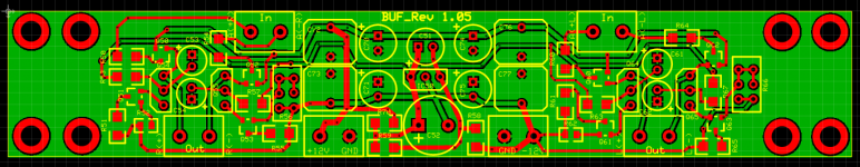
Buffer bare PCB
Hi All,
I take some time to redesign the PCB and I am glad to make it available for how wish to realize the buffer circuit as per carlsors design.
The board have eight mounting holes that can fit the DAC board or the motherboard and measure 145 X 25 mm.
The in, out and +/-12V connections are 5,08 mm.
I don't have the exact price of the board that will be relevant to the amount of boards that I will order to the manufacturer.
With the minimum quantity to place the order of 10 boards I can suppose that will not be more then 20/22 USD each (+shipping).
I will keep the GB open up to January 5th.
Please add here you nickname and quantity:
emyeuoi (x1)
Thanks and Regards,
Enrico
Attachments
Sterlingmck x2emyeuoi (x1)
PET-240 x1
Myint67x1
Juancho x2
Stijn001 x1
- Home
- Source & Line
- Digital Line Level
- Upgraded Single Board PCM1794 NOS DDDAC