emyeuoi (x1)
PET-240 x1
Myint67x1
Juancho x2
Stijn001 x1
Sterlingmck x2
BDL x1
mbcoffman x2
chancenvergeber 1x
PET-240 x1
Myint67x1
Juancho x2
Stijn001 x1
Sterlingmck x2
BDL x1
mbcoffman x2
chancenvergeber 1x
Buffer
Hi Carlsor,
Is the buffer useful when plugged directly into the amp, so without the cinemags? And will, in the case of two decks, be any profit too when using the extra buffer?
Thanks for all your ideas, as you know, I followed your 1/2 clock-delay workout too, with great succes!
Waiting now for a good pin 20 solution.
Happy holidays,
Ed
Last edited:
Buffer Board Circuit
Summary: Doede recommends that at least 4 DAC boards are needed to properly drive an output transformer. This Buffer enables one DAC board to drive an output transformer. Four of us have experienced different prototype versions of this buffer circuit on single board DACs. All agree that the buffer provides a totally neutral, uncolored and detailed sound. The two of us with Cinemags hear deeper and tighter bass with more musical energy than from a single board DAC without a buffer.
This Buffer is NOT a true I/V circuit. No conversion to single ended although capacitor output through one side of each differential output is permitted. No elimination of the 2.7V DAC output signal reference to ground with the buffer output voltage being even slightly higher due to JFET operation at less than Idss current. No gain and no analog filter.
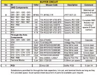
Circuit Description: The buffer circuit consists of BF862 JFET’s loaded by cascoded CCS BF862’s. The matched BF862’s sets I use are all operating at 70-80% of their Idss which is supposed to provide the best sq. See circuit below. The TL431 provides a fixed voltage reference to the gates of the four ZTX450 CCS cascode transistors which make the JFET CCS function even more constant. The PCM1794 chips output experience no load except for the Rload resistors and JFET gates which is negligible.
This Buffer is designed to provide differential outputs to transformers like the Cinemag CMLI-15/15B and to output capacitors. There are 20 ohm pots on one side of each of the differential output buffers to adjust the +/- differential output offset to near 0.0mv.
PCB: Enrico has made a Buffer PCB available for a group buy. This is great because this buffer is very difficult to make with SMD adaptor boards on a perf board.
SMD Parts: This project requires soldering of surface mount SOT-23 JFET's and 1206 Susumu RG resistors. These are large as far as SMD components go, but proper SMD soldering practices must be used to not destroy components. The Idss of BF862 JFET's can vary as much as 25% from one to the next from purchased ribbon strips. I can make available sets of matched BF862 JFET’s including spares. I can also provide the SMD Susumu RG resistors if this helps. This is all detailed in the buffer BOM below.
Power Supply: A +12V/-12V power supply must be provided for the 60ma buffer circuit requirement. The +12V supplying the Main board can be used for the +12V. I use a Pos/Neg Salas board pair that shares the same transformer used for the Salas 8V supply to the DAC analog circuits. The DC grounds from the various power supplies must be connected together in one place.
I will also post step-by-step instructions for checking out, adjusting and testing the Buffer PCB and its components.
Summary: Doede recommends that at least 4 DAC boards are needed to properly drive an output transformer. This Buffer enables one DAC board to drive an output transformer. Four of us have experienced different prototype versions of this buffer circuit on single board DACs. All agree that the buffer provides a totally neutral, uncolored and detailed sound. The two of us with Cinemags hear deeper and tighter bass with more musical energy than from a single board DAC without a buffer.
This Buffer is NOT a true I/V circuit. No conversion to single ended although capacitor output through one side of each differential output is permitted. No elimination of the 2.7V DAC output signal reference to ground with the buffer output voltage being even slightly higher due to JFET operation at less than Idss current. No gain and no analog filter.
Circuit Description: The buffer circuit consists of BF862 JFET’s loaded by cascoded CCS BF862’s. The matched BF862’s sets I use are all operating at 70-80% of their Idss which is supposed to provide the best sq. See circuit below. The TL431 provides a fixed voltage reference to the gates of the four ZTX450 CCS cascode transistors which make the JFET CCS function even more constant. The PCM1794 chips output experience no load except for the Rload resistors and JFET gates which is negligible.
This Buffer is designed to provide differential outputs to transformers like the Cinemag CMLI-15/15B and to output capacitors. There are 20 ohm pots on one side of each of the differential output buffers to adjust the +/- differential output offset to near 0.0mv.
PCB: Enrico has made a Buffer PCB available for a group buy. This is great because this buffer is very difficult to make with SMD adaptor boards on a perf board.
SMD Parts: This project requires soldering of surface mount SOT-23 JFET's and 1206 Susumu RG resistors. These are large as far as SMD components go, but proper SMD soldering practices must be used to not destroy components. The Idss of BF862 JFET's can vary as much as 25% from one to the next from purchased ribbon strips. I can make available sets of matched BF862 JFET’s including spares. I can also provide the SMD Susumu RG resistors if this helps. This is all detailed in the buffer BOM below.
Power Supply: A +12V/-12V power supply must be provided for the 60ma buffer circuit requirement. The +12V supplying the Main board can be used for the +12V. I use a Pos/Neg Salas board pair that shares the same transformer used for the Salas 8V supply to the DAC analog circuits. The DC grounds from the various power supplies must be connected together in one place.
I will also post step-by-step instructions for checking out, adjusting and testing the Buffer PCB and its components.
Attachments

Last edited:
emyeuoi (x1)
PET-240 x1
Myint67x1
Juancho x2
Stijn001 x1
Sterlingmck x2
BDL x1
mbcoffman x2
chancenvergeber 1x
carlsor x1
PET-240 x1
Myint67x1
Juancho x2
Stijn001 x1
Sterlingmck x2
BDL x1
mbcoffman x2
chancenvergeber 1x
carlsor x1
Ed,
I have never plugged the DDDAC or Buffer directly to an amp. The same issues would apply in either case with the output differential signal being 2.7-2.8 volts above DAC signal ground. This is highly dependent on the amp/preamp design whether this would work or whether the buffer would help. It shouldn't make anything worse. The buffer is NOT short circuit protected and a BF862 could fail if an output is shorted. The PCM1794 is a current limited device.
Doede recommends at least 4 DACs to drive a transformer so I have to assume a 2 DAC unit would be benefitted. I hope someone tries the buffer on a 4 DAC setup to find out if there is any benefit in sq.
emyeuoi (x1)
PET-240 x1 + 1 set JFETS + 1 set Susumu
Myint67x1
Juancho x2
Stijn001 x1
Sterlingmck x2
BDL x1
mbcoffman x2
chancenvergeber 1x
carlsor x1
Thanks for the assistance with the JFETS and SMD resistors carlsor!
PET-240 x1 + 1 set JFETS + 1 set Susumu
Myint67x1
Juancho x2
Stijn001 x1
Sterlingmck x2
BDL x1
mbcoffman x2
chancenvergeber 1x
carlsor x1
Thanks for the assistance with the JFETS and SMD resistors carlsor!
emyeuoi (x1)
PET-240 x1 + 1 set JFETS + 1 set Susumu
Myint67x1
Juancho x2
Stijn001 x1
Sterlingmck x2
BDL x1
mbcoffman x2
chancenvergeber 1x
carlsor x1
naimster x2
PET-240 x1 + 1 set JFETS + 1 set Susumu
Myint67x1
Juancho x2
Stijn001 x1
Sterlingmck x2
BDL x1
mbcoffman x2
chancenvergeber 1x
carlsor x1
naimster x2
emyeuoi (x1)
PET-240 x1 + 1 set JFETS + 1 set Susumu
Myint67x1
Juancho x2
Stijn001 x1
Sterlingmck x2
BDL x1
mbcoffman x2
chancenvergeber 1x
carlsor x1
naimster x2
kurand x1 + 1 set JFETS + 1 set Susumu
PET-240 x1 + 1 set JFETS + 1 set Susumu
Myint67x1
Juancho x2
Stijn001 x1
Sterlingmck x2
BDL x1
mbcoffman x2
chancenvergeber 1x
carlsor x1
naimster x2
kurand x1 + 1 set JFETS + 1 set Susumu
emyeuoi (x1)
PET-240 x1 + 1 set JFETS + 1 set Susumu
Myint67x1
Juancho x2
Stijn001 x1
Sterlingmck x2
BDL x1 + 1 set JFETS + 1 set Susumu
mbcoffman x2
chancenvergeber 1x
carlsor x1
naimster x2
kurand x1 + 1 set JFETS + 1 set Susumu
PET-240 x1 + 1 set JFETS + 1 set Susumu
Myint67x1
Juancho x2
Stijn001 x1
Sterlingmck x2
BDL x1 + 1 set JFETS + 1 set Susumu
mbcoffman x2
chancenvergeber 1x
carlsor x1
naimster x2
kurand x1 + 1 set JFETS + 1 set Susumu
emyeuoi (x1)
PET-240 x1 + 1 set JFETS + 1 set Susumu
Myint67x1
Juancho x2
Stijn001 x1
Sterlingmck x2 + 2 set JFETS + 2 set Susumu
BDL x1
mbcoffman x2
chancenvergeber 1x
carlsor x1
naimster x2
kurand x1 + 1 set JFETS + 1 set Susumu
PET-240 x1 + 1 set JFETS + 1 set Susumu
Myint67x1
Juancho x2
Stijn001 x1
Sterlingmck x2 + 2 set JFETS + 2 set Susumu
BDL x1
mbcoffman x2
chancenvergeber 1x
carlsor x1
naimster x2
kurand x1 + 1 set JFETS + 1 set Susumu
emyeuoi (x1)
PET-240 x1 + 1 set JFETS + 1 set Susumu
Myint67x1
Juancho x2
Stijn001 x1
Sterlingmck x2 + 2 set JFETS + 2 set Susumu
BDL x1
mbcoffman x2
chancenvergeber 1x
carlsor x1
naimster x2
kurand x1 + 1 set JFETS + 1 set Susumu
PCB= 16
Parts= 4
PET-240 x1 + 1 set JFETS + 1 set Susumu
Myint67x1
Juancho x2
Stijn001 x1
Sterlingmck x2 + 2 set JFETS + 2 set Susumu
BDL x1
mbcoffman x2
chancenvergeber 1x
carlsor x1
naimster x2
kurand x1 + 1 set JFETS + 1 set Susumu
PCB= 16
Parts= 4
Sorry, I have to withdraw my order.
emyeuoi (x1)
PET-240 x1 + 1 set JFETS + 1 set Susumu
Myint67x1
Juancho x2
Stijn001 x1
Sterlingmck x2 + 2 set JFETS + 2 set Susumu
BDL x1
mbcoffman x2
carlsor x1
naimster x2
kurand x1 + 1 set JFETS + 1 set Susumu
PCB= 15
Parts= 4
emyeuoi (x1)
PET-240 x1 + 1 set JFETS + 1 set Susumu
Myint67x1
Juancho x2
Stijn001 x1
Sterlingmck x2 + 2 set JFETS + 2 set Susumu
BDL x1
mbcoffman x2
carlsor x1
naimster x2
kurand x1 + 1 set JFETS + 1 set Susumu
PCB= 15
Parts= 4
CCS Circuit PCB - GB
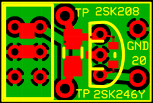
I redesign the original CCS PCB removing the original cascode, relevant LED and resistor.
The board can accept through holes or SMD parts for all the components:
- 2SK246Y through holes or 2SK208 SMD
- Fix resistor smd (1206 or 0805) or through holes at the the TP points
- The trimmer that can be substitute with the fix value smd (0805)
Pin20 and GND connections are 5,08 mm.
Dimension: 15mm X 10mm
As per the Buffer board I don't have the price.
Due to the dimension of the board I suggest to keep the minimum quantity to place the order at 30 boards (30 boards = expected 8/9 USD). In any case, if the GB will not reach the 20 boards, I will inform everybody about the final price and I will ask confirmation before to place the order.
Without saying, the shipping cost will not apply for the boards shipped with the Buffer boards 🙂
I will keep the GB open up to January 5th.
Please add here you nickname and quantity and keep the list separated from the buffer:
emyeuoi (CCS x2)
Thanks and Regards,
Enrico
Attachments
CCS Board
Because 2 CCS boards are needed for each DAC board, I anticipate that more than 30 will be desired. Can you provide a cost estimate per board if 50 are desired? Or 80?
It looks all installation possibilities are included in this CCS board layout.
The solder pads for the 2SK208 SMD JFET will be much easier to use than a perf hole board.
I plan to measure exactly what resistance is needed to operate each of my 2SK208”O” to get 0.40ma at 2.4V and obtain the two resistor values that add up to each desired resistance. I will install each pair of SMD resistors in series including the SMD resistor pads that can be used in place of the trimmer pot.
emyeuoi (CCS x2)
carlsor CCS x4
Because 2 CCS boards are needed for each DAC board, I anticipate that more than 30 will be desired. Can you provide a cost estimate per board if 50 are desired? Or 80?
I can estimate that for 50 boards should not be more than 6 USD and for 80 not more than 4USD
emyeuoi (x1)
PET-240 x1 + 1 set JFETS + 1 set Susumu
Myint67x1
Juancho x2
Stijn001 x1
Sterlingmck x2 + 2 set JFETS + 2 set Susumu
BDL x1
mbcoffman x2
carlsor x1
naimster x2
kurand x1 + 1 set JFETS + 1 set Susumu
brettlb x1
PCB= 16
Parts= 4
PET-240 x1 + 1 set JFETS + 1 set Susumu
Myint67x1
Juancho x2
Stijn001 x1
Sterlingmck x2 + 2 set JFETS + 2 set Susumu
BDL x1
mbcoffman x2
carlsor x1
naimster x2
kurand x1 + 1 set JFETS + 1 set Susumu
brettlb x1
PCB= 16
Parts= 4
Juancho CCS x 4Because 2 CCS boards are needed for each DAC board, I anticipate that more than 30 will be desired. Can you provide a cost estimate per board if 50 are desired? Or 80?
It looks all installation possibilities are included in this CCS board layout.
The solder pads for the 2SK208 SMD JFET will be much easier to use than a perf hole board.
I plan to measure exactly what resistance is needed to operate each of my 2SK208”O” to get 0.40ma at 2.4V and obtain the two resistor values that add up to each desired resistance. I will install each pair of SMD resistors in series including the SMD resistor pads that can be used in place of the trimmer pot.
emyeuoi (CCS x2)
carlsor CCS x4
emyeuoi (x1)
PET-240 x1 + 1 set JFETS + 1 set Susumu
Myint67x1
Juancho x2
Stijn001 x1
Sterlingmck x2 + 2 set JFETS + 2 set Susumu
BDL x1 + 1 set JFETS + 1 set Susumu
mbcoffman x2
carlsor x1
naimster x2
kurand x1 + 1 set JFETS + 1 set Susumu
brettlb x1
PCB= 16
Parts= 5
PET-240 x1 + 1 set JFETS + 1 set Susumu
Myint67x1
Juancho x2
Stijn001 x1
Sterlingmck x2 + 2 set JFETS + 2 set Susumu
BDL x1 + 1 set JFETS + 1 set Susumu
mbcoffman x2
carlsor x1
naimster x2
kurand x1 + 1 set JFETS + 1 set Susumu
brettlb x1
PCB= 16
Parts= 5
- Home
- Source & Line
- Digital Line Level
- Upgraded Single Board PCM1794 NOS DDDAC