The ADAU1701 with its I2S port easily allows 4in6Out configuration with external ADC and TI DACs. I mentioned TI DACs because their latest series of DACs do not need external op-amp based LPFs.
The sigmadsp platform is really cool!
Does anyone know of open source surround decoder for this platform?
The sigmadsp platform is really cool!
Does anyone know of open source surround decoder for this platform?
Which TI DACs have the built in LPFs?
Thanks
Thanks
The ADAU1701 with its I2S port easily allows 4in6Out configuration with external ADC and TI DACs. I mentioned TI DACs because their latest series of DACs do not need external op-amp based LPFs.
The sigmadsp platform is really cool!
Does anyone know of open source surround decoder for this platform?
TI DAC with LPF
PCM510xA
Which TI DACs have the built in LPFs?
Thanks
PCM510xA
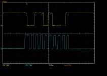
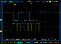
I am having issue with my second board, Ada doesn't seem to respond on i2c bus. Adau1701 is running and generates clock just fine. Eeprom can be written to and read from on the same bus. I even replaced Ada with different part to no avail. Also tried all available i2c adresses without any luck. Scope on sda and scl shows there is activity on both lines when I press read registers in sigma Studio.
Sent from my ZTE A2017G using Tapatalk
Sent from my ZTE A2017G using Tapatalk
Attachments
Last edited:
I am having issue with my second board, Ada doesn't seem to respond on i2c bus. Adau1701 is running and generates clock just fine. Eeprom can be written to and read from on the same bus. I even replaced Ada with different part to no avail. Also tried all available i2c adresses without any luck. Scope on sda and scl shows there is activity on both lines when I press read registers in sigma Studio.
Sent from my ZTE A2017G using Tapatalk
Are you going direct (3.3V/SV2) or through the level-shifter (5V/JP3) circuitry? If I remember correctly SV2 (e.g. the USBi connector) is directly connected to the ADAU1701, whereas the I2C pins on JP3 are connected via a level shifting (e.g. 5v -> 3.3v) circuit.
I'd check for continuity between SV2 and the I2C pins on the ADAU1701 (22/23). If you're outputting a 5V I2C TTL onto JP3 - then scope at SV2 - do you see a 3.3V SDA/SCL?
Maybe try using an Arduino to poke the board using 5V I2C on JP3 - in case the traces to SV2 are damaged?
Thanks for the response, you might be onto something. The board that works is freedsp classic, the one that doesn't is classic smd one. I don't see level shifters between Ada and USBi on either schematics. It seems there are only between Ada and arduino. I'm not sure how classic works then without shifters... They both seem similar in that respect.
Sent from my ZTE A2017G using Tapatalk
Sent from my ZTE A2017G using Tapatalk
Thanks for the response, you might be onto something. The board that works is freedsp classic, the one that doesn't is classic smd one. I don't see level shifters between Ada and USBi on either schematics. It seems there are only between Ada and arduino. I'm not sure how classic works then without shifters... They both seem similar in that respect.
Sent from my ZTE A2017G using Tapatalk
I'm confused. The classic will work with both 3.3 and 5V TTL for I2C as it has shifters. USBi: 3.3V and JP3 5V.
What is your I2C source ?
Which of the SMD boards are you using - balanced or unbalanced?
I'm confused. The classic will work with both 3.3 and 5V TTL for I2C as it has shifters. USBi: 3.3V and JP3 5V.
What is your I2C source ?
Which of the SMD boards are you using - balanced or unbalanced?
I'm using classic (working) and classic SMD A, both unbalanced. I2C source is USBi programmer.
In both schematics I see direct connections for SDA and SCL between ADAU and USBi connector. JP3 is for Arduino afaik, which I don't use, and there I do see level shifters (2N7000?). EEPROM is also connected to 3V3 on the same bus as ADAU and works fine without shifters.
Is classic SMD A supposed to work at all with USBi, if it does not have level shifters? Or is there 3.3V version of USBi programmer that works with classic SMD A board?
I think the usbi is a 3.3v part (I don't have one) as sv2 on the classic board is directly connected to the adau1701. Only the pins on jp3 go through the level shifter.
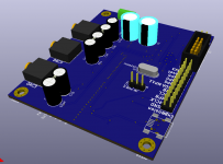
USB to FreeDSP PCB almost done.
What are you using for USB->I2S? My project is going to implement audio-widget as I understand it to be the most open isochronous platform for USB->I2S.
*edit*
I need to do a better job reading - I realize now you're using the PCM2707 is your USB->I2S solution. : -)
You may be interested in looking at the AMB Zeta1. It's pretty awesome and can be hacked to work with a freedsp classic, providing a greater range of configuration (e.g. upto 192khz / 24bit).
Last edited:
What are you using for USB->I2S? My project is going to implement audio-widget as I understand it to be the most open isochronous platform for USB->I2S.
*edit*
I need to do a better job reading - I realize now you're using the PCM2707 is your USB->I2S solution. : -)
You may be interested in looking at the AMB Zeta1. It's pretty awesome and can be hacked to work with a freedsp classic, providing a greater range of configuration (e.g. upto 192khz / 24bit).
Thanks, this really is very interesting. Is there any DIY project around this? I would not like to buy a finished product, but rather to build and integrate into mine.
Thanks, this really is very interesting. Is there any DIY project around this? I would not like to buy a finished product, but rather to build and integrate into mine.
On AMB's website he has the full schematic for it, but not board layout. I believe it's actually based on another implementation of audio-widget / sdr-widget for which there may be a layout floating around. That said, it's really just the amtel avr with a clock for usb, and supporting circuits (e.g. 3v3 regulator etc). You'll still need to supply the 24.576 / 22.5792 clocks (which I believe actually need to be /2 when fed to the MCU e.g. 12.288 for the 24.576 and 11.2896 for 22.5792).
For my project I'm still deciding if I'll use his board or implement the functionality direct on my PCB. The board at the very least makes prototyping easy.
Is there uac2 driver for Windows 10 already? I am putting this on my pcb.
Sent from my ZTE A2017G using Tapatalk
I think windows 10 actually has native uac2 support now, hence the lack of a specific driver.
I think windows 10 actually has native uac2 support now, hence the lack of a specific driver.
Here's a pretty good starting point:
http://www.pavouk.org/hw/audiosystem20/en_at32uc3a3256usbi2s.html
I'm a bit skeptical about all this 24bit/192KHz playback hype - I think it makes sense only for recording. But hey, since this seems simple and cheap to implement, why not?
Here's a pretty good starting point:
http://www.pavouk.org/hw/audiosystem20/en_at32uc3a3256usbi2s.html
I'm a bit skeptical about all this 24bit/192KHz playback hype - I think it makes sense only for recording. But hey, since this seems simple and cheap to implement, why not?
I think it depends on your hearing and the end to end audio chain, but I can actually hear the difference, but I have to play the same 2 second sample at different encoding rates multiple times. The Verge recently did a blind test on this, and a significant number of people could hear the difference (I aced it as well). I'm surprised by the results, however, as I figured most people were running 48khz output, which means that the high bitrate stuff was being downsampled. For me running linux with pulse audio, I have it setup with 192khz output - so most things it ends up upsampling, unless it's already 192khz.
There was another test I did with the 2l test audio - and here again in some samples I could tell the difference.
But in the end, if the entire audio chain isn't great, then you probably won't be able to differentiate the end result. I was able to differentiate using the ADUA1701's internal DAC (on a freedsp classic board, connected to a headphone amp, and over ear cans), as well as using the amb gamma 1.5 - which also uses the same audiowidget for i2s, but uses a wolfson wm8740 dac and an AD8397 opamp to drive the cans. The ADAU was driven by a 12.288mhz XO vs 24.576 on the gamma 1.5.
Both DACs when driven at 192khz were able to produce a signal that allowed me to differentiate encode rate - but just barely. The difference is what I'd describe as modulation step function. E.g. where I was able to pick it out most was changes in frequency on string instruments, where it appeared both at lower bitrates that the frequency change happened as very high speed steps, whereas when driving at 192khz I was not able to detect the steps with my ears.
For me there are two questions: Is there an audible difference? Yes, absolutely.
Is the difference with the extra complexity? I guess it depends on the target application, but given the difference in cost for something I'm going to spend so much time playing with, why not go or the best?
")
- Home
- Source & Line
- Digital Line Level
- freeDSP - an open source 2-in 4-out digital crossover board