If you are using the old Driscoll oscillator TWTMC-D you don't need the sine to square converter board since its output is CMOS.
Then you need the DIL adapter TWTMC-DIL to fit Ian's board and no power supply is needed.
The problem is that I don't know if Ian's boards manage the clock switching between the sample rate families.
If so you have no problem since the board will select the right clock according to the sample rate family and no short circuit will occurr.
If not so you will get a short circuit between the two oscillators because they are both active at the same time.
So you need extednal circuit to manage the clock selection, just like the circuit implemented in the D&D board (you need 5V signal to switch).
Is someone knows how Ian's boards works please help.
If you would use the new Driscoll oscillator you need the sine to square converter because its output is sine wave.
Then you should use a pair of TWTMC-STS (SX and/or DX according to Ian's board layout).
If you install the sine to square converter as is, it's powered by Ian's board.
If you would like to use extenal power supply you have to disconnect the Vcc pin of the TWTMC-STS (simply don't install it and provide external 3V3 power supply).
About clock switching the situation is exactly the same I have described above, it depends on Ian's board.
Although you could modify D&D board to manage the new Driscoll oscillator, if you need external switching I would not use the D&D board.
For this purpose the TWTMC-FSDO-S has been designed.
My understanding is the same as Markw4. I also have the FifoPi Q1 or 1st version. Hence why I am trying to use the enable pins of the two crystals on the FifoPi to switch the relay on the D&D board to select between the 45 and 49MHz crystals. I measured and the XO pins of the two crystals are shorted on the FifoPi Q1, so you have to switch externally.
Andrea, I still need to try the optocouplers to level shift the 3v3 to 5v. Originally I thought it would work as the upper TTL threshold of the FAN3240 ic is max 2v, but I want the isolation anyway, so I will try it when I get the chance in the next few days.
Andrea, I still need to try the optocouplers to level shift the 3v3 to 5v. Originally I thought it would work as the upper TTL threshold of the FAN3240 ic is max 2v, but I want the isolation anyway, so I will try it when I get the chance in the next few days.
Hello,
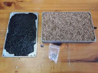
Yesterday i received some cork panels to make a '' soundproof enclosure '' for the aluminium clock boxes.
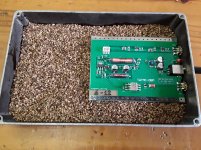
I also got a shoebox volume of '' grinded cork '' which is use to completely bury the circuit boards in the aluminium stomping boxes.
So far i only closed two doubler boxes and when you give them a gentle knock you can not hear that it is a metal box!
You just put a first layer of cork particles. Then guide the SMA connectors to the holes in the box . Taking good care that the print is fully supported by the cork. Then add extra cork up to the rim make it even an have a level that needs a very tiny amount of pressure to get an airtight closure.
So it looks like it is going to work perfectly.
If Doede bought the same circuits he can compare his solution with mine.
Greetings, Eduard
Yesterday i received some cork panels to make a '' soundproof enclosure '' for the aluminium clock boxes.
I also got a shoebox volume of '' grinded cork '' which is use to completely bury the circuit boards in the aluminium stomping boxes.
So far i only closed two doubler boxes and when you give them a gentle knock you can not hear that it is a metal box!
You just put a first layer of cork particles. Then guide the SMA connectors to the holes in the box . Taking good care that the print is fully supported by the cork. Then add extra cork up to the rim make it even an have a level that needs a very tiny amount of pressure to get an airtight closure.
So it looks like it is going to work perfectly.
If Doede bought the same circuits he can compare his solution with mine.
Greetings, Eduard
Hello Simon,
From the information published by Andrea and some serious users of the clocks we can conclude that everything matters.
The box i am using is already a bit more acoustic " inert" because the way it has been produced and designed.
I didn't expect that adding the cork particles would give this much improvement. JUST the change in sound when knocking on a box filled with cork was really big. On top of that cork is a natural product which could be better sound wise than an artificial fabric. Remember removing plastic foil wrapped around electrolytic caps?
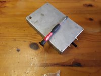
I made the hole for the powerplug a bit bigger so it can be passed without making any contact with the aluminium. This can cause the escape of some cork particles so i will have to add some nail polish around the tiny opening to keep the cork inside.
Once the plug is inserted the opening is covered.
Greetings,Eduard
From the information published by Andrea and some serious users of the clocks we can conclude that everything matters.
The box i am using is already a bit more acoustic " inert" because the way it has been produced and designed.
I didn't expect that adding the cork particles would give this much improvement. JUST the change in sound when knocking on a box filled with cork was really big. On top of that cork is a natural product which could be better sound wise than an artificial fabric. Remember removing plastic foil wrapped around electrolytic caps?
I made the hole for the powerplug a bit bigger so it can be passed without making any contact with the aluminium. This can cause the escape of some cork particles so i will have to add some nail polish around the tiny opening to keep the cork inside.
Once the plug is inserted the opening is covered.
Greetings,Eduard
Attachments
Hello Simon,
The rather basic things Andrea added to tackle the temperature/vibrations will of course be a good start.
But because lots of other '' designing issues '' have been so thoroughly investigated and executed because all of them seem to add a tiny bit more to the final result my idea was to do a little more by using the cork particles. These particles just consist of '' pure cork '' so it doesnt contain glue.
The cork panels i ordered to make a kind of cabinet with 6 compartments are made by heating up cork particles which will make the natural resin present in the cork come outside. This resin will work as a kind of glue.
The panels appear to have a more open structure than i expected so i am not sure if gluing them together in a kind of drawer cabinet will work. The initial idea was to create a rectangular '' hole '' for each aluminium box so the box will be softly '' choked '' by the surrounding cork.
Probably i am going to glue 10 and/or 20 mm thickness panels to the individual boxes and make two separate packages. Each package one clock and two doubler boxes being hold together by a nice red ribbon.
Greetings, Eduard
Hi Andrea, a question regarding your TWTMC-D. I am having some issues getting the 45MHz one working. It was at 49.2MHz when R1=670R, R2=180, C1=8.2p, C2=2.2p C3=5.6p, L2=18u, L4=1.5u. Sometimes it doesn't seem to oscillate at all.
What do you think need to adjust to get 45MHz? I was sure I had it working before I tried to integrate it in the dac [emoji20].
What do you think need to adjust to get 45MHz? I was sure I had it working before I tried to integrate it in the dac [emoji20].
TWTMC-D
OK, I got it working again! Replacing C3 with the same value, or maybe my memory was not correct and it was actually a different value, or tolerances. But for others, the values I posted work for me now.
Now to figure out the actual switching circuit. I tested with 3V3 from a bench supply, and it works. I have to figure out why it is not working from the enable pins from the FifoPi. The rest of the DAC was at home, and I was testing at work as my workshop and scope are in boxes until we move to a larger place I will still do the Optocoupler circuit to test.
Hi Andrea, a question regarding your TWTMC-D. I am having some issues getting the 45MHz one working. It was at 49.2MHz when R1=670R, R2=180, C1=8.2p, C2=2.2p C3=5.6p, L2=18u, L4=1.5u. Sometimes it doesn't seem to oscillate at all.
What do you think need to adjust to get 45MHz? I was sure I had it working before I tried to integrate it in the dac [emoji20].
OK, I got it working again! Replacing C3 with the same value, or maybe my memory was not correct and it was actually a different value, or tolerances. But for others, the values I posted work for me now.
Now to figure out the actual switching circuit. I tested with 3V3 from a bench supply, and it works. I have to figure out why it is not working from the enable pins from the FifoPi. The rest of the DAC was at home, and I was testing at work as my workshop and scope are in boxes until we move to a larger place
I will still do the Optocoupler circuit to test.Hello Andrea,
As you can see i am busy finalizing the clock circuits plus enclosures.
Is it ok for the outside of the 16 volt power plug to touch the enclosure?
Greetings, eduard
Yes as all at 0 volts
- Status
- Not open for further replies.
- Home
- Source & Line
- Digital Line Level
- The Well Tempered Master Clock - Building a low phase noise/jitter crystal oscillator