Yes, but since there is no difference when the harmonics are below the corner frequency of the low pass filter I would assume there will be no difference even if the harmonics reside into the attenuation bandwidth.
Moreover, in case of 5MHz oscillator, high order harmonics (above the corner frequency of the LPF) have less amplitude, so I don't think they can alter the zero crossing.
Moreover, in case of 5MHz oscillator, high order harmonics (above the corner frequency of the LPF) have less amplitude, so I don't think they can alter the zero crossing.
True, but in your case the harmonics are probably not phase modulated, so it is moot case. The need to modulate only harmonic is why I question whether such a condition would occur in reality.
I think Mark is correct, but his example is very hypothetical.
If you would pass the sum of a spectrally pure 24 MHz sine wave and a smaller 72 MHz sine wave with phase noise through a limiter, the noisy 72 MHz signal could indeed shift the zero crossings. The output signal of the limiter would just be a square wave with shifted edges, so there the story about all harmonics being modulated would apply again.
If you would pass the sum of a spectrally pure 24 MHz sine wave and a smaller 72 MHz sine wave with phase noise through a limiter, the noisy 72 MHz signal could indeed shift the zero crossings. The output signal of the limiter would just be a square wave with shifted edges, so there the story about all harmonics being modulated would apply again.
Aaaarghhh, hopeless.
And I thought I was clear with this Collins thing.
You are not supposed to put an ultra wideband signal
into a dumb comparator.
You are not supposed to use an FM radio without
any selectivity . At least you should not complain
about the result.
And I thought I was clear with this Collins thing.
You are not supposed to put an ultra wideband signal
into a dumb comparator.
You are not supposed to use an FM radio without
any selectivity . At least you should not complain
about the result.
Last edited:
Is it correct that the measured increase in phase noise floor is only related to noise floor of the logic used in STS, not strictly a result of sine to square conversion?
Andrea how you think: STS (sine to square converter) must be in DAC (close to Amanero) or it could be near DRIXO and then ~ 50sm RG400 cable after STS to DAC?
Is it correct that the measured increase in phase noise floor is only related to noise floor of the logic used in STS, not strictly a result of sine to square conversion?
No.
My hypothetical example was with a 24Mhz audio clock, so the 3rd harmonic would be up around 72MHz. Wouldn't that get attenuated by the phase measurement input filter?
If we started with a 5Mhz clock then I would have had to specify a higher order harmonic as being phase modulated so as to put it above the input low pass filter cutoff (that is, I would have to do it in order to create a suitable hypothetical question).
Are you describing a combination wave where the harmonic is independently phase modulated from the fundamental? Not just phase shifted? That would require several things to happen just right I suspect, or at least sloppy design (never happens).
1. Open mouth
2. Insert foot
I’m sure to be shot down for presenting such a broad sided barn but it is my understanding that harmonic distortion is just that, harmonics of the fundamental frequency as they are related to it. They don’t wander in frequency unless the fundamental wanders in frequency. Changes in amplitude to the harmonic series from reflections adding and subtracting will produce a differing waveform from the ideal square. This can modulate the rise and fall times of the clock reference. The voltage threshold of a comparator is only ever near zero in a bipolar powered circuit. Typically it is some fixed voltage between logic zero and logic 1, ground and 3.3 or 5 volts for example so 1.75 or 2.5 volts. In truth it is often set lower than 50 % to allow for loading errors and low voltage conditions. Noise on the ground or the power supply including harmonic distortion will introduce timing errors in the crossing detection circuitry that we call phase modulation if repetitive or simply phase noise. Cascading detection stages as well as paralleling drive gates will average and thus minimize these timing errors. Using a good xtall instead of a phase locked loop can also improve the situation. While deemed not important by some absolute frequency stability over time if extended to include the recording clock will bring further benefit especially in non oversampling systems as the necessary steep anti aliasing filters will be able to work as designed. As an aside the original Emulator sampler would vary the playback speed of samples to tune them to the pitches of a keyboard. Each note had its own tuned filters to let the changing frequency of the harmonics through while removing as much aliasing noise as possible.
Andrea how you think: STS (sine to square converter) must be in DAC (close to Amanero) or it could be near DRIXO and then ~ 50sm RG400 cable after STS to DAC?
The STS is a 50 ohm load for the oscillator so I would use the coaxial cable to connect the oscillator to the STS, placing it close to the DAC or the FIFO buffer if you are using one.
Hi Andrea,
I was soldering R1 on the old Discroll board for an AT-Cut 5,6 M hz but I see two different values on the Pdf : in the screen number 5 : it is marked 100 ohms, but in a further page in the assembly guide in a summary screen it is marked 120 ohms (same as 22/24 Mhz AT-cuts)
both will work or you advice one over the second, please ?
Also, is the 10 pF pot is mandatory or just if it doesn't lock ?
many thanks
Is it correct that the measured increase in phase noise floor is only related to noise floor of the logic used in STS, not strictly a result of sine to square conversion?
Since the difference in noise floor is inversely proportional to the slope of the sinusoidal signal (this is what we have observed) I assume that the noise crosses the CMOS device when switching.
The wider the channel opening window, the greater the increase in noise floor.
In fact the lower the frequency of the oscillator the greater the degradation of the noise floor.
However I would not much worried about a noise floor around -160dB, just my opinion.
Hi Andrea,
I was soldering R1 on the old Discroll board for an AT-Cut 5,6 M hz but I see two different values on the Pdf : in the screen number 5 : it is marked 100 ohms, but in a further page in the assembly guide in a summary screen it is marked 120 ohms (same as 22/24 Mhz AT-cuts)
both will work or you advice one over the second, please ?
Also, is the 10 pF pot is mandatory or just if it doesn't lock ?
many thanks
You're right there is an inconsistency between page 8 and page 16.
The right value is 100R, although there will be not much difference using 120R because the value of this resistor is calculated according to the ESR of the crystal, 5/6 MHz and 22/24 MHz AT-Cut crystals have similar ESR.
Usually you don't need the trimmer capacitor, you can just install a fixed capacitor as indicated in the BOM.
Hi Andrea,
The LED doesn't lite on one of my doubling boards. Is this just a power indicator or does it serve some other purpose? Everything sounds fine so I believe the doubler is working just not indicating.
The LED doesn't lite on one of my doubling boards. Is this just a power indicator or does it serve some other purpose? Everything sounds fine so I believe the doubler is working just not indicating.
Hi Stephen,
if you mean D1 it's just a power indicator, while D2 has to lite.
The doubler works correctly even if D1 does not lite.
Can you please check the soldering of D1?
In any case you could replace it with a standard 3mm red LED, the anode (longer leg) is connected to R18.
Sorry for the issue.
if you mean D1 it's just a power indicator, while D2 has to lite.
The doubler works correctly even if D1 does not lite.
Can you please check the soldering of D1?
In any case you could replace it with a standard 3mm red LED, the anode (longer leg) is connected to R18.
Sorry for the issue.
Are you describing a combination wave where the harmonic is independently phase modulated from the fundamental?
Yes, otherwise seems like phase noise measurements should be the same with or without filtering?
Hello,
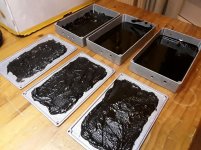
Today i started preparing the so called aluminium stomping boxes. They are used in the entertainment industry for " guitar pedals" i like their industrial looks.
I melted some old vinyl records to give them a kind of vibration killing coating on the box and on the lid.
I have to see if i also need some vinyl on the smaller surfaces too but usually just covering the big panels will do.
The effect of this little vinyl is already clearly to notice. Maybe will use something acting like a gasket between lid and box.
If i can make a kind of airtight enclosure i could use dry sand inside or i will go for cotton/wool "" lining"
Maybe can use a tiny microphone and some acoustic measurement software to see which solution will give the biggest reduction of vibration/sound reaching the microphone buried in the box.
Greetings,Eduard
Attachments
Hello,
There isnt any kind of coating on the aluminium. The surface has been given its look by " tumbling " it in a kind of rotating machine filled with some kind of pebbles. Of course after some time there will be a kind of " thin film" because the metal reacts with the air. But when you close the box you just have to take care that there is a good contact between the two parts. Having less parts will make it easier to get a good screening.
Greetings,Eduard
- Status
- Not open for further replies.
- Home
- Source & Line
- Digital Line Level
- The Well Tempered Master Clock - Building a low phase noise/jitter crystal oscillator