This is a sample I got from HCD and it's a custom part, so any frequency could be available. About a production, the minimum order quantity is 5 pcs and break price are:If thats Hz on the x-axis it's one of the better I have seen. Whats the cost? What frequencies are available? Link?
- 5 pcs 294.10 euro each
- 10 pcs 271.54 euro each
Since it use an SC-cut crystal the oven is essential. SC cuts have an inflection temperature of about 92°C and are very flat at the hotter end, but tail off quickly on the cold end. The proper operating temperature for an SC-cut crystal is usually in the range of 80-100°C, then they are usually used under constant hot temperature, just as in Oven Controlled Crystal Oscillator.Oven is overkill... the usual box and the fact that D/A are are usually used indoors makes it unnecessary.
Note that only SC-cut crystal reaches very high Q (from 300-400k up to 1M and over), which normally allows to get excellent performance in phase noise (frequency domain) and usually low jitter (time domain).
Unfortunately an SC-cut crystal and consequently an OCXO have a disadvantage: the price. For that reason they are not usually implemented in audio application. I remember only a few device, very expensive, using that way; conversely they are often used in professional analog to digital conversion, as the master clock of the entire system.
An OCXO guarantees a very high long term stability, useless in audio digital to analog conversion, but it also guarantees high short term stability in the frequency domain, essential in audio application to get low jitter.
Andrea
backdoor
Hi Ian,
Do I read allright that I have to ground (short) the signal- and the grnd pad of former resistor 22 ? I found out after I placed the connector. But if I shoud short the two, I can make just a grnd connection with pin 4.
Please could you confirm?
Thanks!
Ed
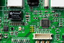
Step1: Remove R22, R23, R24, R25 from PCB. SMT soldering station is recommended tool, but normal solder iron is still OK.
Setp2: Cover the GND pads of R23, R24 and R25 with fine cut high temperature tape to avoid signals short to GND.
Setp3: Solder the 4P SMT PH2.0 header, Pin1 (WS) to R24 signal pad, Pin2 (SD) to R25 signal pad, Pin3 (SCK) to R23 signal pad and Pin4 to both R22 signal pad and GND pad,
Step4: Cut the solder mask paint beside the both GND pads of the header appearing small area of GND copper plate, please be careful no touching any other circuit route.
Step5: Solder the support pads of the header to the appeared GND copper plate. Solder iron with higher power may require. For enough support force, applying compound of strong glue (such as epoxy) is highly suggested for double support.
Step6: Make an I2S cable to introduce an additional I2S input source.
The Digikey P/Ns are:
Connector header: 455-1736-1-ND
House: 455-1164-ND
Terminal pin: 455-1127-2-ND
Ian
Hi Ian,
Do I read allright that I have to ground (short) the signal- and the grnd pad of former resistor 22 ? I found out after I placed the connector. But if I shoud short the two, I can make just a grnd connection with pin 4.
Please could you confirm?
Thanks!
Ed
This is a sample I got from HCD and it's a custom part, so any frequency could be available. About a production, the minimum order quantity is 5 pcs and break price are:
- 5 pcs 294.10 euro each
- 10 pcs 271.54 euro each
Since it use an SC-cut crystal the oven is essential. SC cuts have an inflection temperature of about 92°C and are very flat at the hotter end, but tail off quickly on the cold end. The proper operating temperature for an SC-cut crystal is usually in the range of 80-100°C, then they are usually used under constant hot temperature, just as in Oven Controlled Crystal Oscillator.
Note that only SC-cut crystal reaches very high Q (from 300-400k up to 1M and over), which normally allows to get excellent performance in phase noise (frequency domain) and usually low jitter (time domain).
Unfortunately an SC-cut crystal and consequently an OCXO have a disadvantage: the price. For that reason they are not usually implemented in audio application. I remember only a few device, very expensive, using that way; conversely they are often used in professional analog to digital conversion, as the master clock of the entire system.
An OCXO guarantees a very high long term stability, useless in audio digital to analog conversion, but it also guarantees high short term stability in the frequency domain, essential in audio application to get low jitter.
Andrea
Quite well explained here:
SC-cut Frequency vs. Temperature Curves
Crystal Technology
Only 700$ US$ for a dual clock setup it's a bargain! At these prices I think I will pass
")
Will you compare it with the CCHD-957 in a critical listening test?
Hi Ian,
Do I read allright that I have to ground (short) the signal- and the grnd pad of former resistor 22 ? I found out after I placed the connector. But if I shoud short the two, I can make just a grnd connection with pin 4.
Please could you confirm?
Thanks!
Ed
Yes, R22 short to ground by pin4 of the connector.
Ian
Attachments
Quite well explained here:
SC-cut Frequency vs. Temperature Curves
Crystal Technology
Only 700$ US$ for a dual clock setup it's a bargain! At these prices I think I will pass
Will you compare it with the CCHD-957 in a critical listening test?
I received the sample yesterday, so I have not yet test its sound performance.
This is a custom OCXO, so inevitably it's not a cheap solution.
As I know, nobody produce OCXO at frequencies suitable for digital to analog conversion as a standard item.
BTW I'm following an alternative way to reach similar performance at lower cost, with an high quality AT-cut crystal in a dedicated circuit
http://www.diyaudio.com/forums/grou...hronous-i2s-s-pdif-fifo-kit-group-buy-70.html
This is a sample I got from HCD and it's a custom part, so any frequency could be available. About a production, the minimum order quantity is 5 pcs and break price are:
- 5 pcs 294.10 euro each
- 10 pcs 271.54 euro each
Since it use an SC-cut crystal the oven is essential. SC cuts have an inflection temperature of about 92°C and are very flat at the hotter end, but tail off quickly on the cold end. The proper operating temperature for an SC-cut crystal is usually in the range of 80-100°C, then they are usually used under constant hot temperature, just as in Oven Controlled Crystal Oscillator.
Note that only SC-cut crystal reaches very high Q (from 300-400k up to 1M and over), which normally allows to get excellent performance in phase noise (frequency domain) and usually low jitter (time domain).
Unfortunately an SC-cut crystal and consequently an OCXO have a disadvantage: the price. For that reason they are not usually implemented in audio application. I remember only a few device, very expensive, using that way; conversely they are often used in professional analog to digital conversion, as the master clock of the entire system.
An OCXO guarantees a very high long term stability, useless in audio digital to analog conversion, but it also guarantees high short term stability in the frequency domain, essential in audio application to get low jitter.
Andrea
OK, so You mean that the close in phase noise 0-100 hz is not possible on this level if the crystal is not heated?
/
OK, so You mean that the close in phase noise 0-100 hz is not possible on this level if the crystal is not heated?
/
I mean SC-Cut crystal does not work at ambience temperature.
And I also mean similar phase noise performance is very difficult to reach with an AT-Cut crystal. See Crystek specs and compare with HCD OCXO.
I'm trying to reach something of similar with the Laptech AT-cut crystal, but it's a cold welded and polished crystal that cost 2 times the Crystek.
Without a good crystal you cannot build a good oscillator. PLL or similar solution, do not solve the problem coming from a bad crystal, at least in audio application.
Just another option, this is an OCXO from HCD, and its excellent performance in phase noise.
Do they have any plans for developping the same sort of OCXOs for 22.5792, 45.1584, 90.3168, 24.576, 49.152, 98.304 MHz?
Do they have any plans for developping the same sort of OCXOs for 22.5792, 45.1584, 90.3168, 24.576, 49.152, 98.304 MHz?
They don't develop any OCXO at frequencies suitable for digital audio. That's a custom part they makes on my specs.
BTW, if some folks was interested, we could do a group buy, at least 5 people for any frequency.
At this time I'm building a quiet regulator to supply the OCXO and compare it with other options such as Crystek, Tentlabs and my own design based on Laptech high performance AT-cut crystal.
I'll let you know the sonic results. Lab tests speak for themselves.
Thanks andrea_mori, yes, the PSU is really a challenging for OCXO, from what I know, usually the XO share power with the 'oven".
I'm looking forward to hearing your result.
Regards,
Ian
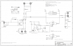
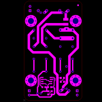
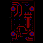
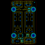
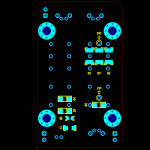
Battery management board PCB V2.0 with an optional dealyed realy
1. I understand the application of the passive battery manage board may not be limited to powering the clock board. To avoid any damage by the power on surge current of charging big capacitors, I include an optional delayed relay to limit the possible high surge current. Even for a clock board, the surge current may still go high if there are some low ESR capacitors on board. The delay time now is 0.5s, but it’s adjustable.
2. Remove some options on V1.0 which may not be used for normal configuration. That makes it easier to setup, clean and less confusion.
3. To make it easier setting up battery arrays, I placed the battery and charger connectors on one side and the output and control voltage connectors on the other side. Stack on top of each other is also available.
All physical dimensions keep same no change.
Hopefully this passive battery management board V2.0 will be available together with the Si570 clock board.
Please let me know for any suggestion and comment.
Ian
Attachments
Last edited:
Ian,
If only clock board is powered by batteries and delayed, is it possible for that to be the problem? Usually clock is the one that has to be powered up first before any other digital circuits? I think I recall info that DAC could have a problem if it powers up before the master clock?
If only clock board is powered by batteries and delayed, is it possible for that to be the problem? Usually clock is the one that has to be powered up first before any other digital circuits? I think I recall info that DAC could have a problem if it powers up before the master clock?
Ian,
If only clock board is powered by batteries and delayed, is it possible for that to be the problem? Usually clock is the one that has to be powered up first before any other digital circuits? I think I recall info that DAC could have a problem if it powers up before the master clock?
Hi AR2,
You are right, the clock should be running priori to all other section of the system before the gone of the reset signal. However, the delayed realy will not delay the power up, it just limits the high surge current for a very short of time (the main realy already switched on). So, I don't think it will cause problem on the start up time of clock board. But I'll double check and make some real measurements on the power on time of the clock board after I get the PCB prototype.
The delayed realy is just an option, if the main relay can handle the surge current, then you may not need the delayed one. But for high current application such as powering a DAC analog power, the dealyed relay will help.
Ian
Last edited:
Ian
As a battery management, should it automatically cut off the battery to prevent over discharge?
That should be the function of a charger. Passive battery management board need to be compatible with different kind of chemicals, as well as different voltage.
Ian
Hi AR2,
You are right, the clock should be running priori to all other section of the system before the gone of the reset signal. However, the delayed realy will not delay the power up, it just limits the high surge current for a very short of time (the main realy already switched on). So, I don't think it will cause problem on the start up time of clock board. But I'll double check and make some real measurements on the power on time of the clock board after I get the PCB prototype.
The delayed realy is just an option, if the main relay can handle the surge current, then you may not need the delayed one. But for high current application such as powering a DAC analog power, the dealyed relay will help.
Ian
Thank you Ian for the response.
AR2
- Home
- Source & Line
- Digital Line Level
- Asynchronous I2S FIFO project, an ultimate weapon to fight the jitter