Here is a very good one with info on how they work: PRS10 - Rubidium Frequency Standard
Dear 1audio,
You really have a wonderful deep understanding on Rubidium discharge lamp calibrated varactor tuned OCXO device. I appreciated your explanation very much.
I read
Model PRS10 - Rubidium Frequency Standard - Operation and Service Manual
and understood that its single calibrating interval is 200ms.
First, I'd be very happy if you could kindly tell me whether my understanding is correct or not.
Second, unfortunately, I have never found the corresponding description on a calibration interval for FE-5680A. Do you have any idea on the value for FE-5680A? How often do you think the base VCXO frequency, 50.255 MHz, is tuned for a Rubidium Physics Package?
Bunpei
Bunpei:
You give me more credit than I'm due. My understanding is pretty limited. I believe the sweeping for finding lock only happens when the system is starting and it would stop when it has a good phase lock but I don't know. As the lamps get old the output decreases and the time to lock will increase. Most of the Rubidiums on eBay have had a lot of service and may be near the end of life for the lamps.
You give me more credit than I'm due. My understanding is pretty limited. I believe the sweeping for finding lock only happens when the system is starting and it would stop when it has a good phase lock but I don't know. As the lamps get old the output decreases and the time to lock will increase. Most of the Rubidiums on eBay have had a lot of service and may be near the end of life for the lamps.
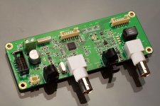
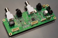
S/PDIF interface board for I2S FIFO project
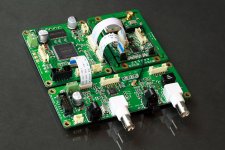
To extend the applications of the FIFO project to the fields other than building or modding a DAC, I need an S/PDIF interface board. So, I designed this one. Working together with the I2S FIFO board and the clock board, it becomes an S/PDIF FIFO.
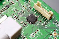
I use TI/BB new generation 216 KHz digital audio interfaces DIX9211 as the S/PDIF transceiver. Actually I built both DIX9211 and WM8805 evaluation boards in advance and did very carefully test before I made the decision. DIX9211 shows bit more stable on coaxial input running at 192 KHz, and it support 176.4 KHz more directly. Importantly, within DIX9211, the DIR and DIT are independent from each other. They have separate I2S ports and MCLK input and output, as well as the channel status buffers, which are the very basic requirements for an asynchronous S/PDIF FIFO. I’m very happy with the performance of DIX9211 so far, although the price is double.
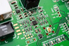
S/PDIF driver is another very significant issue. People usually use CMOS driver such as 74HCU04 doing this kind of job. Functionally, there is no any problem. But I don’t think normal COMS buffers are suitable for low jitter application. Because the bi-phase mark code is mixed with both clock and date, it is very sensitive to the additive jitter along the transmission chain (that’s why the cable and the transformer could be heard). I use a balanced LVPECL driver driving the digital audio transformer into coaxial cable. The sound improved obviously than the CMOS driver, as well as the waveform after 5 feet cable with 75 ohm termination. I will give more details together with schematics and waveforms about this new S/PDIF driver solution later on. To eliminate the additive jitter generated by DIX9211 itself, S/PDIF signal need to be re-clock directly at finial stage by the MCLK from clock board.
The features of the this S/PDIF interface board are as below:
1. Three S/PDIF inputs: coaxial, optical and TTL, could be switched by a button;
2. Two S/PDIF outputs: coaxial and optical;
3. Support Fs (both input and output): 44.1 kHz/16bit(24bit ready), 48 kHz/16bit(24bit ready), 88.2 kHz/24bit, 96 kHz/24bit, 176.4 kHz/24bit, 192 kHz/24bit;
4. I2S FIFO interface;
5. MCLK input port to clock board with dedicated 50 ohm U.FL connector;
6. Low jitter LVPECL S/PDIF driver;
7. S/PDIF source LED indicators;
8. Lock indicator LED;
9. Front panel interface port available for all the LEDs and control button
Working with the FIFO board and clock board, 3 hours bit perfect loop test was passed with up to 192Khz/24 bit setup and for both coaxial and optical connection;
Please reference to the attached pictures. Please note, in the pictures, the FIFO board is already the second edition with S/PDIF board interface, optional U.FL I2S input and bug free.
To extend the applications of the FIFO project to the fields other than building or modding a DAC, I need an S/PDIF interface board. So, I designed this one. Working together with the I2S FIFO board and the clock board, it becomes an S/PDIF FIFO.
I use TI/BB new generation 216 KHz digital audio interfaces DIX9211 as the S/PDIF transceiver. Actually I built both DIX9211 and WM8805 evaluation boards in advance and did very carefully test before I made the decision. DIX9211 shows bit more stable on coaxial input running at 192 KHz, and it support 176.4 KHz more directly. Importantly, within DIX9211, the DIR and DIT are independent from each other. They have separate I2S ports and MCLK input and output, as well as the channel status buffers, which are the very basic requirements for an asynchronous S/PDIF FIFO. I’m very happy with the performance of DIX9211 so far, although the price is double.
S/PDIF driver is another very significant issue. People usually use CMOS driver such as 74HCU04 doing this kind of job. Functionally, there is no any problem. But I don’t think normal COMS buffers are suitable for low jitter application. Because the bi-phase mark code is mixed with both clock and date, it is very sensitive to the additive jitter along the transmission chain (that’s why the cable and the transformer could be heard). I use a balanced LVPECL driver driving the digital audio transformer into coaxial cable. The sound improved obviously than the CMOS driver, as well as the waveform after 5 feet cable with 75 ohm termination. I will give more details together with schematics and waveforms about this new S/PDIF driver solution later on. To eliminate the additive jitter generated by DIX9211 itself, S/PDIF signal need to be re-clock directly at finial stage by the MCLK from clock board.
The features of the this S/PDIF interface board are as below:
1. Three S/PDIF inputs: coaxial, optical and TTL, could be switched by a button;
2. Two S/PDIF outputs: coaxial and optical;
3. Support Fs (both input and output): 44.1 kHz/16bit(24bit ready), 48 kHz/16bit(24bit ready), 88.2 kHz/24bit, 96 kHz/24bit, 176.4 kHz/24bit, 192 kHz/24bit;
4. I2S FIFO interface;
5. MCLK input port to clock board with dedicated 50 ohm U.FL connector;
6. Low jitter LVPECL S/PDIF driver;
7. S/PDIF source LED indicators;
8. Lock indicator LED;
9. Front panel interface port available for all the LEDs and control button
Working with the FIFO board and clock board, 3 hours bit perfect loop test was passed with up to 192Khz/24 bit setup and for both coaxial and optical connection;
Please reference to the attached pictures. Please note, in the pictures, the FIFO board is already the second edition with S/PDIF board interface, optional U.FL I2S input and bug free.
Attachments
Last edited:
Nice looking board!
You know you could implement both S/PDIF RX and TX in the PLD with many benefits. Since you are running a FIFO, so there is no need for clock recovery function of a commercial receiver. In other word, their clock recovery performance is probably not going to make a difference. The open source S/PDIF RX works reliably under 192KHz input with 100MHz system clock. No problem with 176.4KHz, either. You probably don't care about channel status data. Even if you do, it is easy to copy the data from the RX side to the TX. There can be unlimited input channels, and you can still use external re-clocking and buffering for the TX.
Wait... Why would you use a TX since the S/PDIF format is inherent prone to jitter? Shouldn't the output of the FIFO go directly to the DAC?
Do the BNC connectors offer advantages over standard RCA?
Hi 454Casull,
S/PDIF should be treated as RF signal and BNC usually comes with better impedance matching performance than the RCA, says 75 ohm. So, I think that would be one of the advantages.
RCA S/PDIF cables still work if we add BNC/RCA adapters over the BNC connector, I did this way during the functional testing.
Have a good night.
Ian
Do the BNC connectors offer advantages over standard RCA?
The digital transmission of BNC refers to AES at 24Bit/48KHz while RCA refers to S/PDIF at 20Bit/48KHz. [Reference] Some people have talked to me that the jitter of BNC is at the minimum in comparing to AES/EBU(Balanced) or S/PDIF. I have not see any research paper to support. In my practical listening test, I personally cannot hear any difference between BNC and RCA connection.
Isn't this important only for video applications?Hi 454Casull,
S/PDIF should be treated as RF signal and BNC usually comes with better impedance matching performance than the RCA, says 75 ohm. So, I think that would be one of the advantages.
Have a good night.
Ian
Impedance matching is very important for all high frequency RF signal transmission as well as clock signal. It's not for video 'only'Isn't this important only for video applications?
") . Actually S/PDIF signal is not a audio signal. It's kind of bi-phase mark code and should be look upon as a clock signal. If we don't have good impedance matching, the reflecting signal will be added over the clock and introducing more jitter. Ian
. Actually S/PDIF signal is not a audio signal. It's kind of bi-phase mark code and should be look upon as a clock signal. If we don't have good impedance matching, the reflecting signal will be added over the clock and introducing more jitter. Ian
Last edited:
What you say may be quite true - I was thinking of an analog signal...Impedance matching is very important for all high frequency RF signal transmission as well as clock signal. It's not for video 'only'
Erno Borbely famously terminated all his BNC analogue transmission lines as well.
very nice quality boards, keep me in mind for a set when you look to doing a run. or at least le me know the wallet damage and i'll let you know. if its not under NDA i would have no problems soldering my own boards
very nice quality boards, keep me in mind for a set when you look to doing a run. or at least le me know the wallet damage and i'll let you know. if its not under NDA i would have no problems soldering my own boards
Nice thread
A lot to read and a lot to learn
Keep it up guys.
Btw. reading your discussions I ran into a few things, that might to both you guys and me.
The WM8741 chip from Wolfson is described sounding "not clear"
To that I can say that it actually is like that. Both the 8740 and 8741 which i happened to listen to, are pretty dull and lazy to listen to.
I also think that characterizing that as analog sound is wrong. Good analog sound is much more lifelike than this. And actually it is quita a riddle to me how Wolson managed to get reasonably precise digital recordings to sound like this.
In need of an U out chip I would go for CS or AK instead.
About the whole idea with a FIFO of a certain size to minimize jitter, has always been one of my favourite thoughts about digital audio.
But is there any particular reason why you do not talk about up-sampling?
Up-sampling is as far as I know, seen as a very effective way of managing jitter already present in the signal.
Of course it would be even better if it was not there at all, but still it seems very attractive.
Very interesting project, Ian.
I second qusp's recommendation for a GB!
So, Toslink 24/192 is actually feasible using standard Toshiba TORX147/TOTX147 parts? I thought the bandwidth of these parts was not enough and, sadly, the 25Mbps parts (TORX142/TOTX142) have been discontinued.
I second qusp's recommendation for a GB!
Working with the FIFO board and clock board, 3 hours bit perfect loop test was passed with up to 192Khz/24 bit setup and for both coaxial and optical connection;
So, Toslink 24/192 is actually feasible using standard Toshiba TORX147/TOTX147 parts? I thought the bandwidth of these parts was not enough and, sadly, the 25Mbps parts (TORX142/TOTX142) have been discontinued.
At least in Japan, it appears that if you contact an official Toshiba distributor and make a custom purchase order for TOSLINK components that are rated for 192kb operation, it is still possible to order and purchase such components from Toshiba.
Do expect to pay for whatever minimum quantities are required.
hth, jonathan carr
Do expect to pay for whatever minimum quantities are required.
hth, jonathan carr
Erno Borbely famously terminated all his BNC analogue transmission lines as well.
very nice quality boards, keep me in mind for a set when you look to doing a run. or at least le me know the wallet damage and i'll let you know. if its not under NDA i would have no problems soldering my own boards
Hi qusp,
Thanks again for the recommendation of the U.FL connectors. I'm very happy with them. It get the signal improved obviously. I use both U.FL conncetors and cables in almost all of my projects now.
Very glad you want the KIT. Once I go through the fully test on all the second edition PCBs and make sure everything is OK with bug free, I will consider setting up a group buy. I could figure out how much work I have to do going a small quantity production. Don't warry about your wallet, I'll give you a surprise
.Nice looking board!
Wait... Why would you use a TX since the S/PDIF format is inherent prone to jitter? Shouldn't the output of the FIFO go directly to the DAC?
You know you could implement both S/PDIF RX and TX in the PLD with many benefits.
Thanks simmconn,
The S/PDIF interface board is a very flexible design. Basically, on board, it has a DIR and a DIT which are independent from each other. You can use it as a S/PDIF receiver and feed the I2S signal directly to the DAC form the clock board, which might the way you want; or,you can loop the I2S to the S/PDIF board and make it working as a S/PDIF FIFO; and or, your can make it doing both at same time.
Including the S/PDIF receiver and transmitter into FPGA design is a smrt idea. But my considerations in this project are:
1. Actually I can do this, but the problem is I need more logic cells and other resourses. That means I have to use larger CPLD/FPGA than the CPLD I'm useing now. The DIX9211 is just an $5 chip,the cost would be less then enlarging the CPLD/FPGA;
2. My design idea is kind of open concept. I need to keep the S/PDIF board independent from the FIFO and clock board, in case somebody else want to use their own S/PDIF interface solution, or just don't use it at all;
3. Use a commercial IC like DIX9211 is safer for this project, at least it guaranteed fully tested by the group from TI/BB.
Ian
- Home
- Source & Line
- Digital Line Level
- Asynchronous I2S FIFO project, an ultimate weapon to fight the jitter