OK, Sorry for dumb question. But why does the TPA3255 use teo Op-amps, but from what I can see the 3221 does not?.
Cheers
The TPA3255 requires balanced inputs and the two Op Amps are usually included included to convert an SE Input signal to Balanced to drive the amplifier chip. They also provide a buffer / Pre Amp stage that may be required for low level signals often provided by consumer sources. The TPA3255 is expecting to see about 2 volt input signal.
The TPA3221 can accept either Balanced or SE inputs directly so does not require Op Amps to drive the amplifier chip. Also the TPA3221 has more gain so can work with lower input signal levels.
The TPA3221 is aimed at “Consumer” products with the lowest component count whereas the TPA325x is more aimed at professional / Audiophile products and requires more external circuitry and power supplies in order to produce a working amplifier.
.

Hei guys just found this new amazing tpa3221 finished amp
US $166.00 50%OFF | Fever digital power amplifier TPA3251 ultra-clear HIFI digital power amplifier, high power and small size
Fever digital power amplifier TPA3251 ultra clear HIFI digital power amplifier, high power and small size|Home Automation Kits| - AliExpress
US $166.00 50%OFF | Fever digital power amplifier TPA3251 ultra-clear HIFI digital power amplifier, high power and small size
Fever digital power amplifier TPA3251 ultra clear HIFI digital power amplifier, high power and small size|Home Automation Kits| - AliExpress
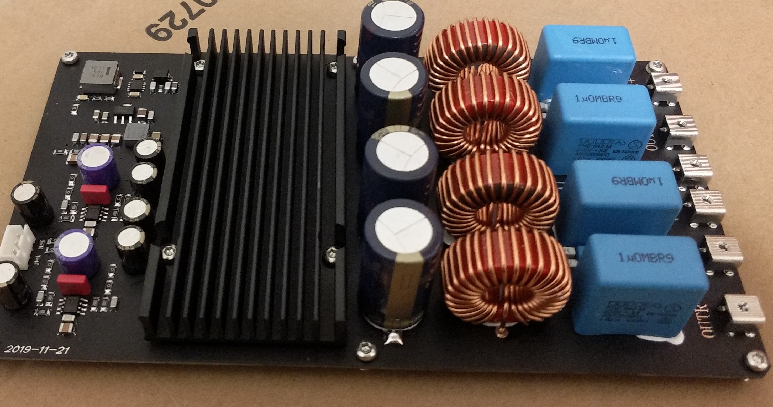

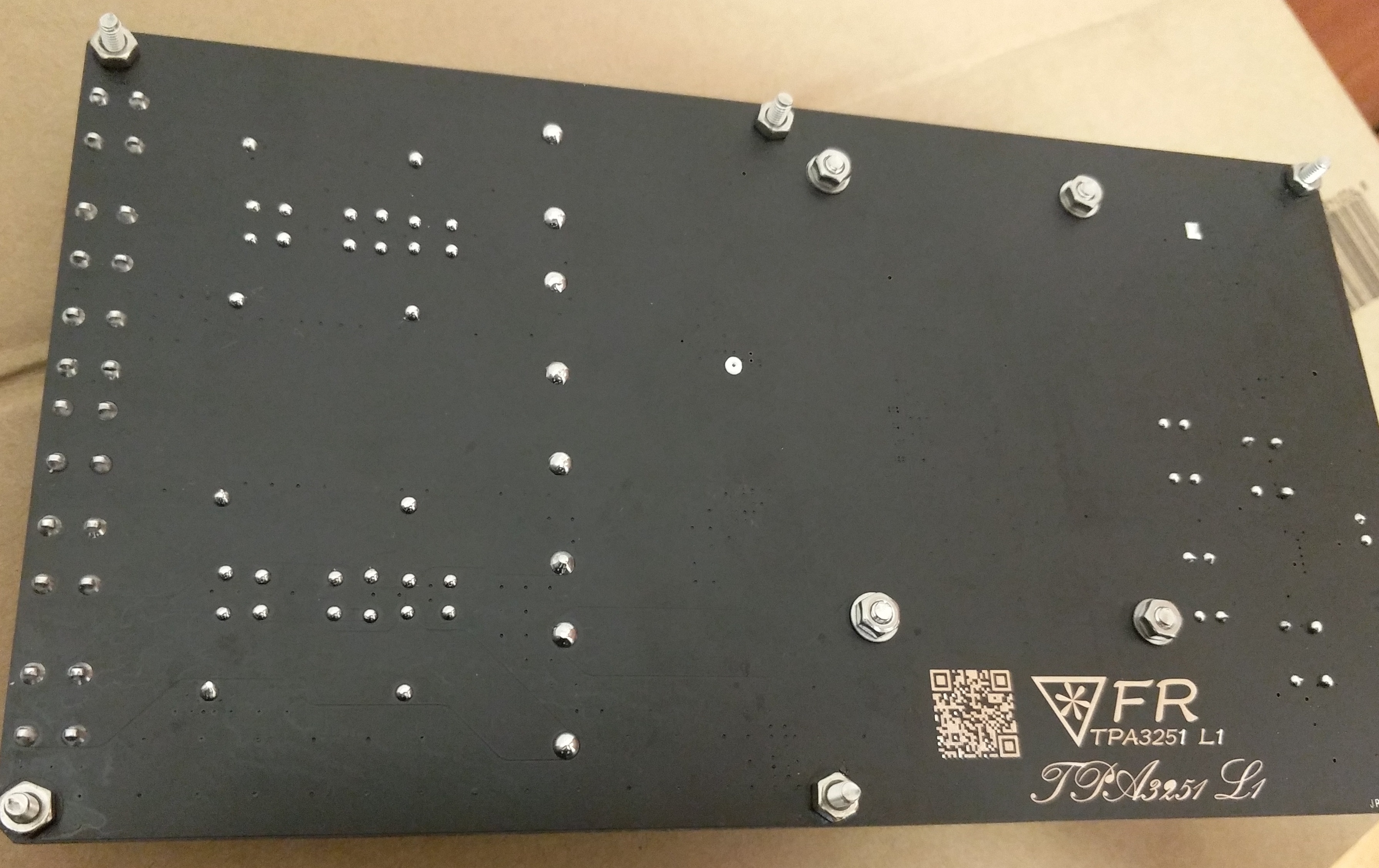
Hi! I bought the Sunbuck tpa3221 module to test outfor an upcoming active speaker build for a family member. I really, really like the amp! It sounds very good. Crisp and clean deep bass, very nice even fr and great imaging and dead quiet when not fed a signal. My only gripe is the big pop when turned on. Does anybody have an idea as how to mitigate this? I like tinkering but i have literally no usable knowledge of electronics... 
 I drive it with a 24vdc MeanWell wall wart.
I tried with a cap in the rest/mute position which worked great with the same looking TPA3255 card, but no good.
Photos show that part of the board and it seems not mostly unpopulated.
Btw: It leaves the TPA3116 far, far behind it imo. Just does everything better.
I drive it with a 24vdc MeanWell wall wart.I tried with a cap in the rest/mute position which worked great with the same looking TPA3255 card, but no good.
Photos show that part of the board and it seems not mostly unpopulated.
Btw: It leaves the TPA3116 far, far behind it imo. Just does everything better.
Attachments
For those who haven't seen it.
Half price of the other linked above
Fever digital power amplifier TPA3221 high-definition high-power HIFI power amplifier
Fever digital power amplifier TPA3221 high definition high power HIFI power amplifier|Home Automation Kits| - AliExpress
Half price of the other linked above
Fever digital power amplifier TPA3221 high-definition high-power HIFI power amplifier
Fever digital power amplifier TPA3221 high definition high power HIFI power amplifier|Home Automation Kits| - AliExpress
Last edited:
Personal Build for TPA3221
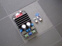
Pictured below are my own design and layout. They borrow strongly from the development board for TPA3221 and SIDEGIG-XOVEREVM modules. The amplifier module can take both TPA3220 and 3221 devices.
The primary reason for their creation is for use within a portable speaker. Driving factors in this project are weight and power consumption/efficiency. The TPA322x seemed like a good mix between power output and idle consumption. Using an active crossover helps with both weight and overall power consumption and gives me a chance to tweak the filter response after the build using SMD components. Adding power rail shutdown and other status signals allows me to reduce standby power to near zero when I add a bluetooth audio controller. The Coilcraft dual inductors and 47uF ceramics reduce board space and weight - my ears cannot discern any difference and seem like a decent trade-off for this project. High sensitivity drivers allow further reduction in weight and power consumption for comparable volumes. The speaker in test is very loud inside.
Idle current (bench PSU reading) for the two boards is around 50mA from 17 to 32V and does not really change accross this range.
The modular approach was used to allow reuse of the amplifier design - stereo amplifier can be created using another plug-in module. The amplifier board was designed on 2 layer 2oz with some components on underside, whilst the crossover is 4 layer 1oz with all components on top side.
I made a mistake with the differential output amplifier on the xover - the inverting input feedback comes from the non-inverting output. This makes sense now - as that is negative feedback but I designed the board with inverting to negated output giving positive feedback. You can see the wire mods for this.
I also ordered the VSSOP package of the OPA1692 amplifier as the TI ordering number sucks. OPA1692ID / DR for the SOIC whereas OPA1692IDGKR / DGKT for the VSSOP. Why they didn't give the SOIC another character after the D is beyond me.
New layout planned if I build anymore than the 5 boards I have.
Overall it's a nice amp to design with - and decent enough to do a power efficient layout.
Attachments

This looks quite neat, and I like the separate audio frontend module for its flexabilty. Did you layout with kiCAD?Personal Build for TPA3221
Pictured below are my own design and layout. They borrow strongly from the development board for TPA3221 and SIDEGIG-XOVEREVM modules. The amplifier module can take both TPA3220 and 3221 devices.
The primary reason for their creation is for use within a portable speaker. Driving factors in this project are weight and power consumption/efficiency. The TPA322x seemed like a good mix between power output and idle consumption. Using an active crossover helps with both weight and overall power consumption and gives me a chance to tweak the filter response after the build using SMD components. Adding power rail shutdown and other status signals allows me to reduce standby power to near zero when I add a bluetooth audio controller. The Coilcraft dual inductors and 47uF ceramics reduce board space and weight - my ears cannot discern any difference and seem like a decent trade-off for this project. High sensitivity drivers allow further reduction in weight and power consumption for comparable volumes. The speaker in test is very loud inside.
Idle current (bench PSU reading) for the two boards is around 50mA from 17 to 32V and does not really change accross this range.
The modular approach was used to allow reuse of the amplifier design - stereo amplifier can be created using another plug-in module. The amplifier board was designed on 2 layer 2oz with some components on underside, whilst the crossover is 4 layer 1oz with all components on top side.
I made a mistake with the differential output amplifier on the xover - the inverting input feedback comes from the non-inverting output. This makes sense now - as that is negative feedback but I designed the board with inverting to negated output giving positive feedback. You can see the wire mods for this.
I also ordered the VSSOP package of the OPA1692 amplifier as the TI ordering number sucks. OPA1692ID / DR for the SOIC whereas OPA1692IDGKR / DGKT for the VSSOP. Why they didn't give the SOIC another character after the D is beyond me.
New layout planned if I build anymore than the 5 boards I have.
Overall it's a nice amp to design with - and decent enough to do a power efficient layout.
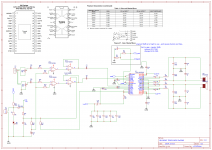
That circuitry around TL084 looks rather pointless to me. The input amps will not work at all due to missing feedback. The following buffer stage do not make any sense. The hole arrangement does not provide single-ended to symmetrical double ended output. TL084 will add noise. So what is it good for? All in all you can remove the hole thingy for better results.schematic of the tpa3116 changed
Hello, figured I'd post here instead of a new thread. I bought an aliexpress tpa3221 special and was wondering how much current they can take or what is the "wise" amount for these amps? I'll be using batteries for my project so they're rated at 3.6V and 8A. Could such a board handle 16A if wired in parallel?
You need to reach at least the 7V recommended minimum for the TPA3221. 8A current rating should be fine for the minimum voltage you need, if you want to be safe add more batteries in parallel (but keep the voltage at 7 V min). Ultimately the amount of power the chip can deliver depends on the voltage you feed it, so that configuration would not yield much output

Hi,Hi! I bought the Sunbuck tpa3221 module to test outfor an upcoming active speaker build for a family member. I really, really like the amp! It sounds very good. Crisp and clean deep bass, very nice even fr and great imaging and dead quiet when not fed a signal. My only gripe is the big pop when turned on. Does anybody have an idea as how to mitigate this? I like tinkering but i have literally no usable knowledge of electronics...
I tried with a cap in the rest/mute position which worked great with the same looking TPA3255 card, but no good.
Photos show that part of the board and it seems not mostly unpopulated.
Btw: It leaves the TPA3116 far, far behind it imo. Just does everything better.
I have amps just like these and my red caps are junk. If I touch them or jiggle them around, the output is changed or muted.
I want to change them, and I wonder if I can get any improvement in sound quality if I choose better ones. Which type would you guys recommend?
Seems like the quotes do not show the images, so I'll just attach one from the internet.
Attachments
- Home
- Amplifiers
- Class D
- TPA3221