These days SMPSUs are so ubiquitous and cheap that there really isn't another economical solution to powering a modest power-level amp. However they're all CM noise generators which leads to potential SQ issues with SE input connections as the noise current from the SMPSU travels down the shield of the input cable. An input transformer through providing galvanic isolation helps reduce the noise current substantially and thus reduces SQ degradation.
In this design the input transformer also provides signal attenuation seeing as the TDA8932 in BTL mode has way too high gain (36dB). Added to attenuation there's also SE-bal conversion and the final element is the creation of an input low-pass filter by virtue of the trafo's leakage inductance. The trafo thus realizes four design goals in a single component.
The other point of interest in this design is the use of two regulators - one for the signal supply and a second for the output power supply. Subjectively the regulators make a significant improvement in dynamics - an earlier iteration of this amp used an LC filter to derive the signal supply and there's no doubt that the SQ with the regulator was more enjoyable.
PCBs are due back in about 5 days. I estimate the BOM cost using parts from Taobao to be under $6 but there is the business of winding the transformer to be taken care of. Once I have the PCB working as expected, if there's interest I plan to open a thread in the Bazaar to make kits and finished/tested boards available.
<Update> I've already received interest so here is the thread where the kits are offered for sale : https://www.diyaudio.com/forums/ven...ed-tda8932-25w-8r-mono-amp-kits-new-post.html
Attachments
Last edited:
The input transformer has two sites on the PCB to allow either EP17 or EE25 trafos to be fitted. Winding your own trafo isn't really too difficult - the part I found to be the biggest challenge when I started out was keeping track of turns. Eventually I decided to buy a machine like this one to keep track of turns automatically.
1pc NZ 1 Manual hand dual purpose Coil counting and Coil Winding Machine|Power Tool Accessories| - AliExpress
There's a big advantage to having a machine with a chuck - that is you can wind even very small bobbins (like EP17 for example which has an inner diameter of 6mm) through use of a drill bit as mandrel. EE25 has a square section with 7.2mm diameter - for this I use a 7mm drill bit with some sticky tape wound around to enlarge the diameter enough to get a decent grip on the bobbin.

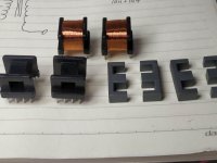
For those as yet unfamiliar with ferrite cored magnetics, here are the component parts of the EE25 transformer. The material is 10k ferrite - a high permeability blend so as to get the highest shunt inductance. Its downside is a lower peak flux (~0.25T) compared to the more common forms of ferrite.
Turns on the primary are 1200 and 1200 using 0.07mm wire. I've laid this down in two individual windings to see if I can create selectable gain. Secondary is 144+144 (CT) with 0.19mm. There are about 4 layers of transformer tape between pri and sec.
Turns on the primary are 1200 and 1200 using 0.07mm wire. I've laid this down in two individual windings to see if I can create selectable gain. Secondary is 144+144 (CT) with 0.19mm. There are about 4 layers of transformer tape between pri and sec.
Attachments
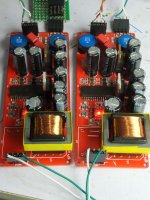
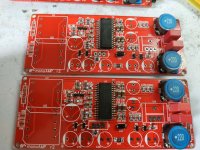
A stereo pair now built up. One of the things I need to decide is an appropriate supply voltage for the chip - too high and it'll overheat and the music will have holes in it. Too low and we won't be getting the most power possible out of it. Hence lots of listening ahead 🙂 i'm kicking off running about 21V which corresponds to ~14VRMS and 25W into 8ohms at onset of clip.
Initial impressions - very favourable.
Initial impressions - very favourable.
Attachments
Are there any gains to be had from using a 'quieter' 3 term reg in place of the LM317? Or even using something like an offboard series regulator?
What are the current requirements for the 2 rails you power with the regs?
Cheers
What are the current requirements for the 2 rails you power with the regs?
Cheers
Last edited:
On the output side power (U4 on schematic) there won't be any gains as the load current induced noise is orders of magnitude greater than the reg's own noise. The signal side reg (U3) might benefit from lower noise - I am not using the textbook configuration for this reg, rather a zener 'assist' to achieve lower noise down to lower frequencies.
I'd definitely not want to go offboard for U4 as the output impedance is the determinant of the rail noise. But if an offboard reg had remote sensing it would be OK. Moving U3 off-board I doubt will impact the SQ.
Current requirements - U3 is a relatively constant ~50mA, U4 depends on the signal but with an 8ohm load could peak between 2 and 3A. Note I'm using an LD1085 for U4 at present not the LM317 shown on the schematic. The former has a higher maximum output current and a lower drop-out voltage.
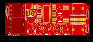
Next generation PCB
A few changes on this PCB which (fingers crossed) will be the ultimate revision before transitioning to a commercial thread.
The twin primaries of the trafo now can be configured by 0R resistor to give 6dB gain variation (either 1V or 2V input sensitivity for full output). The NP0 output caps have been replaced by a Wima polyester to shave a significant sum from the BOM. A diode between the two supply rails turned out necessary to protect the chip against the signal supply being present when the output supply isn't. The LD1085 has been equipped with a heatsink to allow more robust operation over a wider range of load impedances, supply voltages and crest factors of music. The aim is to run from a 24V SMPSU with around 21V being fed to the TDA8932.
Attachments
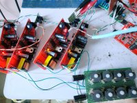
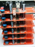
I couldn't resist trying out four of these amps with a passive line-level XO - bottom right in the pic. Four inductors per channel give an LR4 splitter designed from Passive Crossover Design Equations Formulas Calculator - Two Way Fourth Order Network Gaussian Linear Phase Butterworth Legendre. I've a few hacked active speakers lying around where I've ditched the electronics but hung on to the enclosures and drivers, this configuration makes a straightforward solution to getting those boxes back into circulation. I'm wondering why it has been that the active speakers I've bought have been better value than many passive ones even once the electronics (which normally sucks) has been ditched?
Without separate gain controls the tweeters turned out rather hot - easily fixed in Foobar with some tweaks to the EQ function (in DSP). The same functionality allows adding BSC. Longer term I'm planning a transformer to do the tweeter level adjustment.
Without separate gain controls the tweeters turned out rather hot - easily fixed in Foobar with some tweaks to the EQ function (in DSP). The same functionality allows adding BSC. Longer term I'm planning a transformer to do the tweeter level adjustment.
Attachments
Last edited:
Transformers are due in any day now 😎
I ran a rudimentary heating test - no thermal problem with 10dB crest factor tone burst (average output power 2.5W, peak 25W) in ambient 32oC. Both chip and reg heatsink were touchable so seems like some margin for loads below 8R or less than ideal ventilation.
I ran a rudimentary heating test - no thermal problem with 10dB crest factor tone burst (average output power 2.5W, peak 25W) in ambient 32oC. Both chip and reg heatsink were touchable so seems like some margin for loads below 8R or less than ideal ventilation.
Attachments
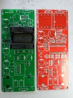
Test PCB just came in
Since the TDA8932s come to us with rather unknown provenance I figured it would be prudent to give them a functional test before putting them into kits. Hence the need for a test PCB with a socket - what we don't know yet is how the extra inductance of the socket will affect operation of the chip. Once we've built one up, we may know the answer to this 🙂
Transformers apparently are delayed due to my giving the factory a slightly over-optimistic target spec for the primary inductance. With a slight relaxation on that parameter we may get them in a day or so.
Attachments
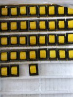
Transformers are here at last....
Now I just need to make a few measurements to check that they're close enough to the hand-wound ones I've been using so far. The leakage inductance on these is part of an input low-pass filter so will affect the FR. I'd also like to make an input impedance measurement of this amp vs frequency to check its in-system compatibility. Some classD amps aren't the most friendly loads to drive so I'd like to know how this one compares.
Now I just need to make a few measurements to check that they're close enough to the hand-wound ones I've been using so far. The leakage inductance on these is part of an input low-pass filter so will affect the FR. I'd also like to make an input impedance measurement of this amp vs frequency to check its in-system compatibility. Some classD amps aren't the most friendly loads to drive so I'd like to know how this one compares.
Attachments
What is included in the kit?
And i am very curious about the difference in sound and spec with the standard design. Did you already some comparisation?
And i am very curious about the difference in sound and spec with the standard design. Did you already some comparisation?
The kit will include all the parts to build two amp PCBs. All you will need to add to have a working stereo amp will be a 24VDC power supply.
As regards comparison I haven't listened to the DS implementation for many years now. But I remember the high frequencies being so harsh that I only wanted to use the TDA8932 for bass duty and a classAB chipamp for the tweeter on my two-ways. Now the HF is pristine like a mountain stream. Dynamics overall are improved immensely by regulating the two supplies.
As regards comparison I haven't listened to the DS implementation for many years now. But I remember the high frequencies being so harsh that I only wanted to use the TDA8932 for bass duty and a classAB chipamp for the tweeter on my two-ways. Now the HF is pristine like a mountain stream. Dynamics overall are improved immensely by regulating the two supplies.
$30 is a very good price for the kit. I think it is a ideal kit for people who like to tryout there first smd solder skills and get a great amp. I like to buy one kit and compare it with my se813 tube amp or gremlin class d amp.
Shipping will of course put up the price. I agree its a fairly accessible way to 'get your feet wet' if you've not done SMD soldering before. And the SQ is exceptionally good irrespective of price - its better than my ICEpower amp although not as powerful.
If you are ready to sell send me a PM.
About the output power, 99,9% of the time i do not need more then 10Watt.
About the output power, 99,9% of the time i do not need more then 10Watt.
We are doing a re-spin on the PCBs to tidy things up at present, we should be ready to ship out kits in a week.
- Home
- Amplifiers
- Class D
- Transformer input TDA8932 mono amp